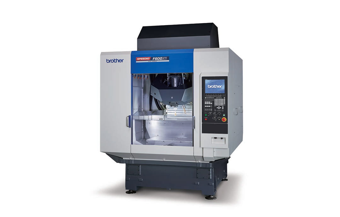
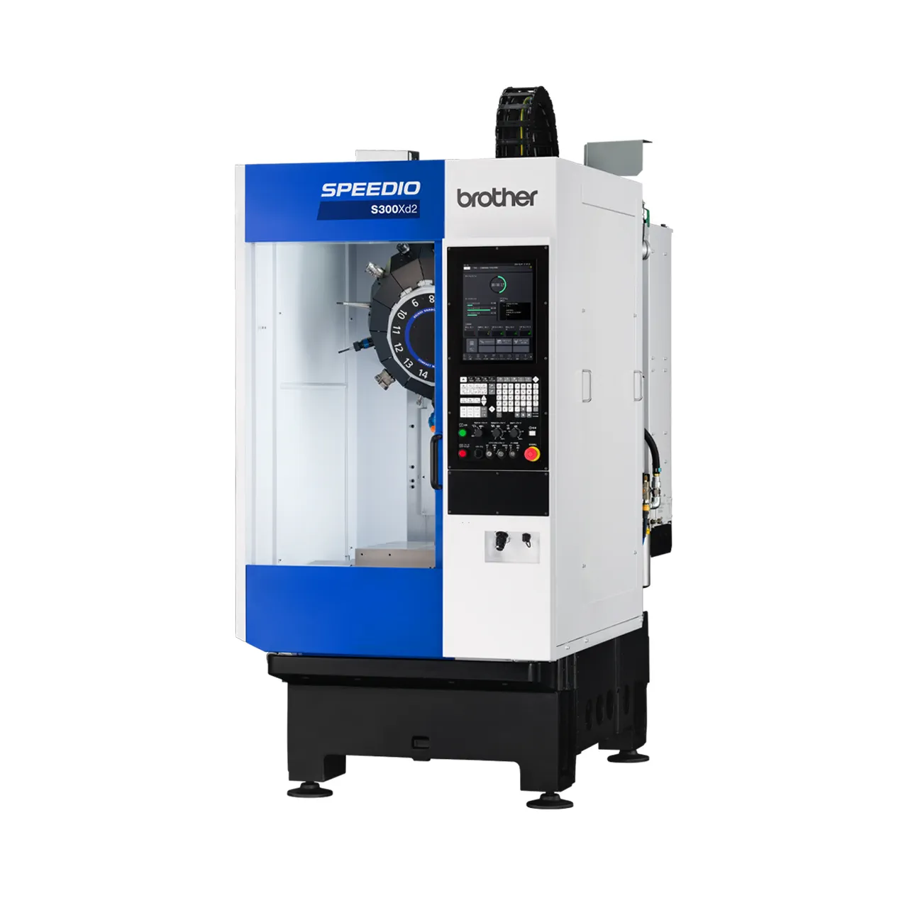
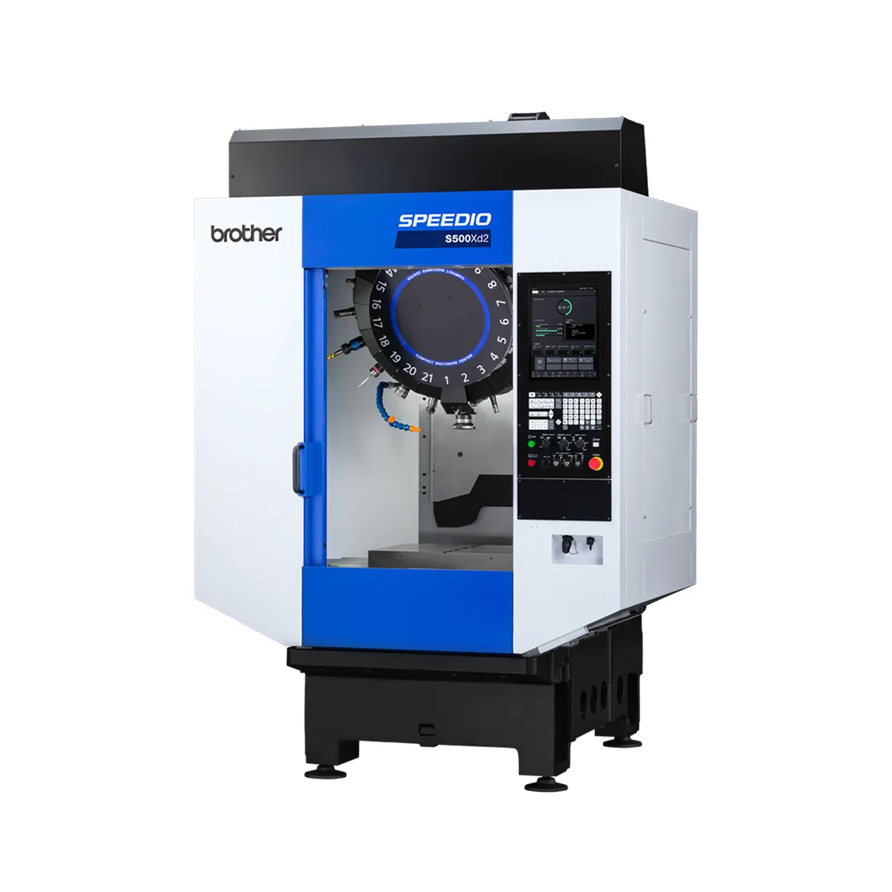
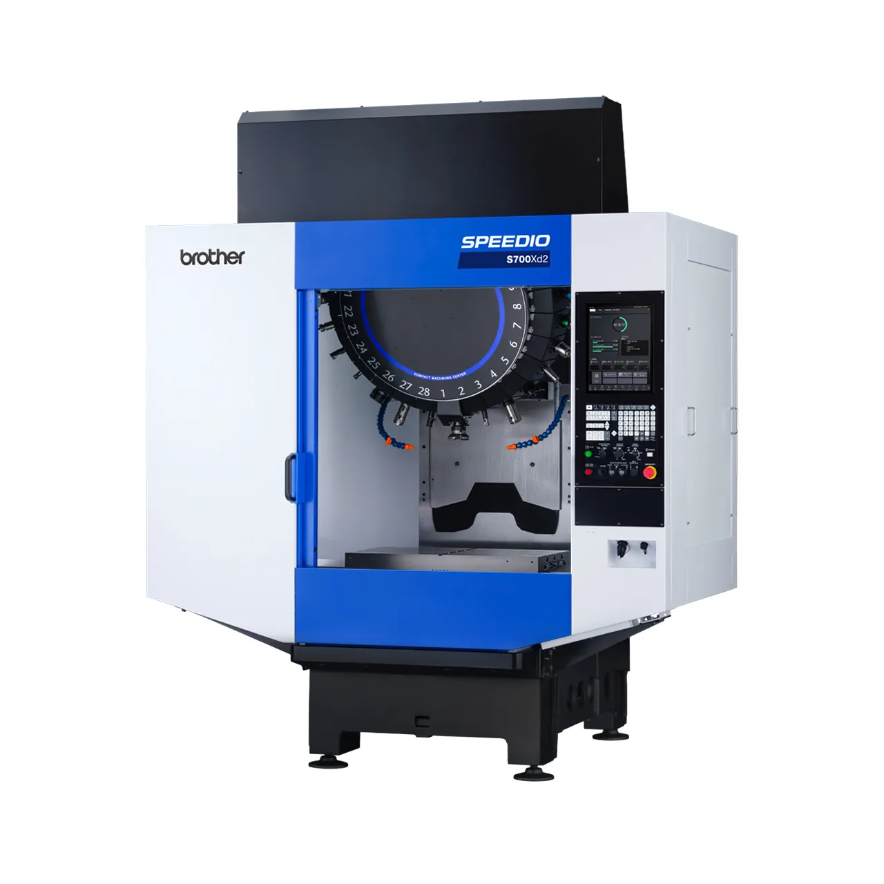
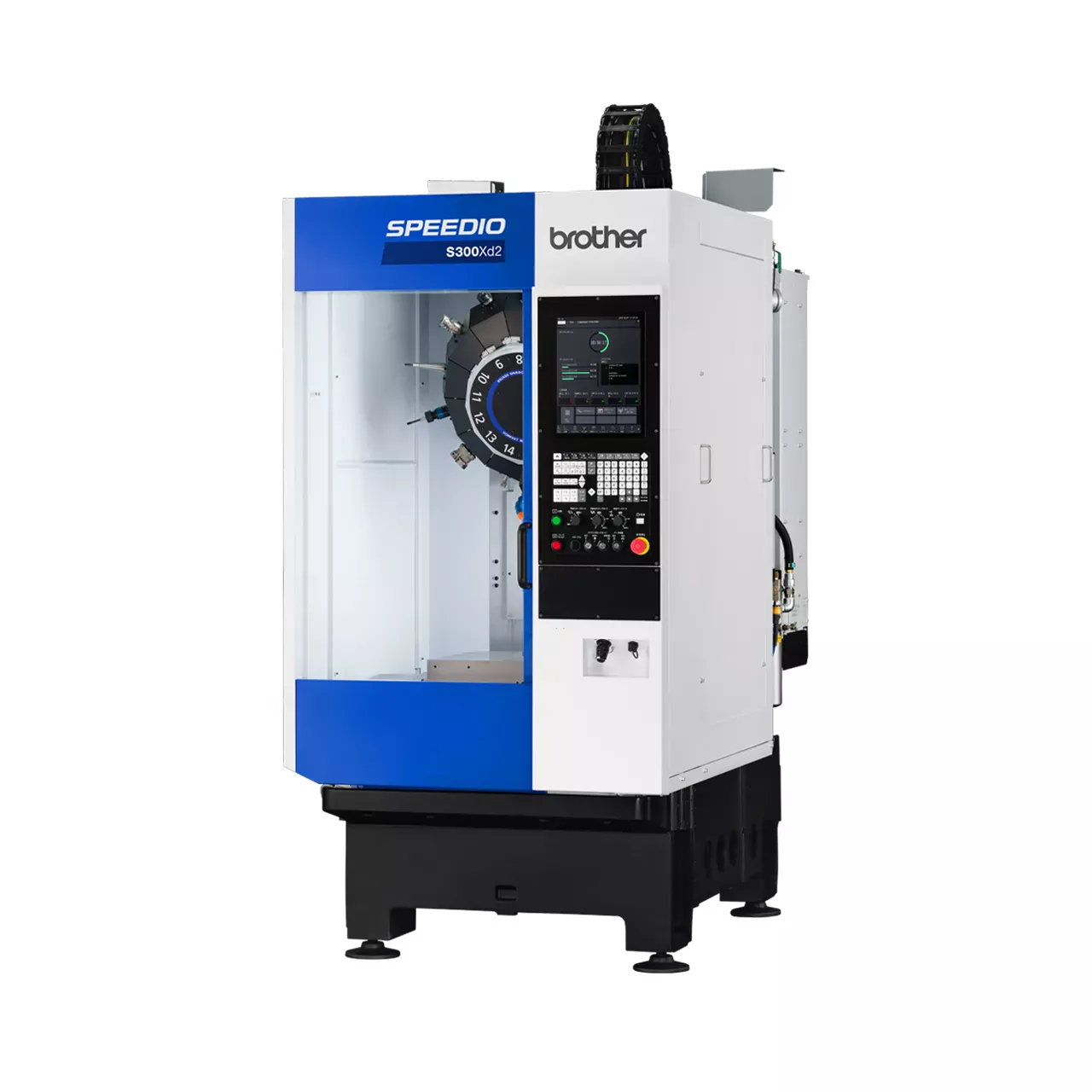
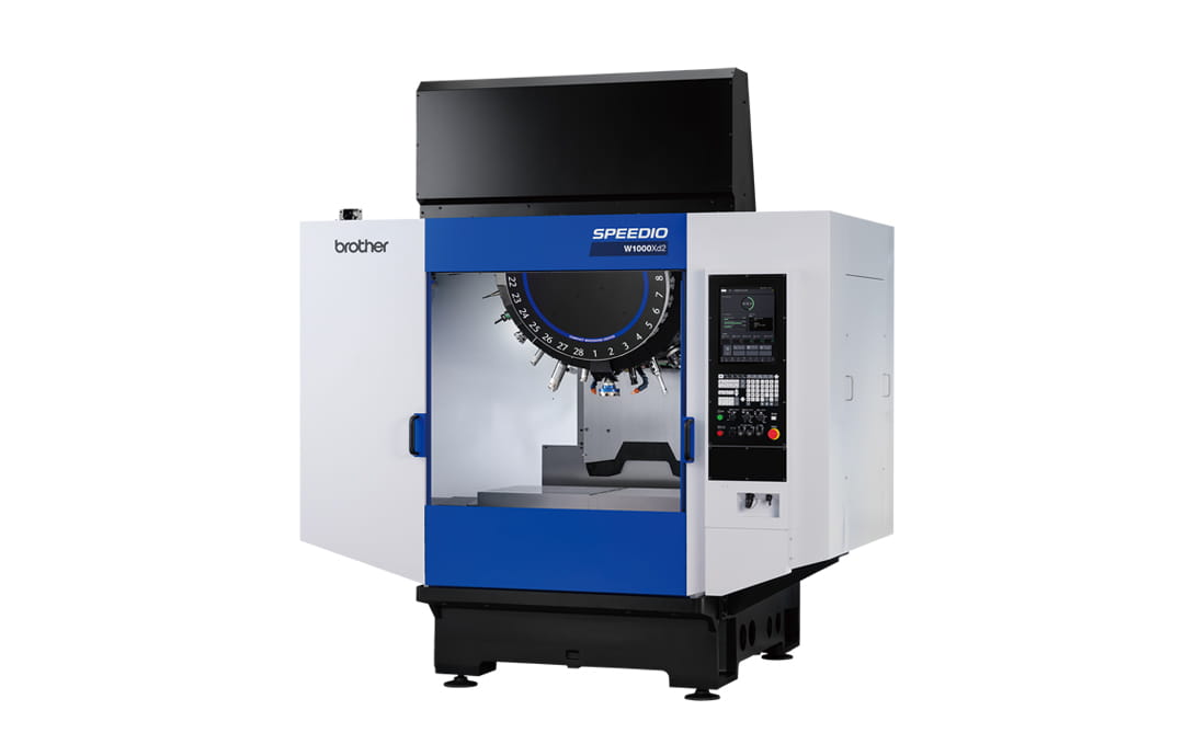
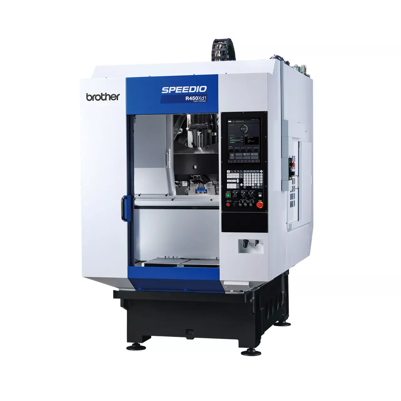
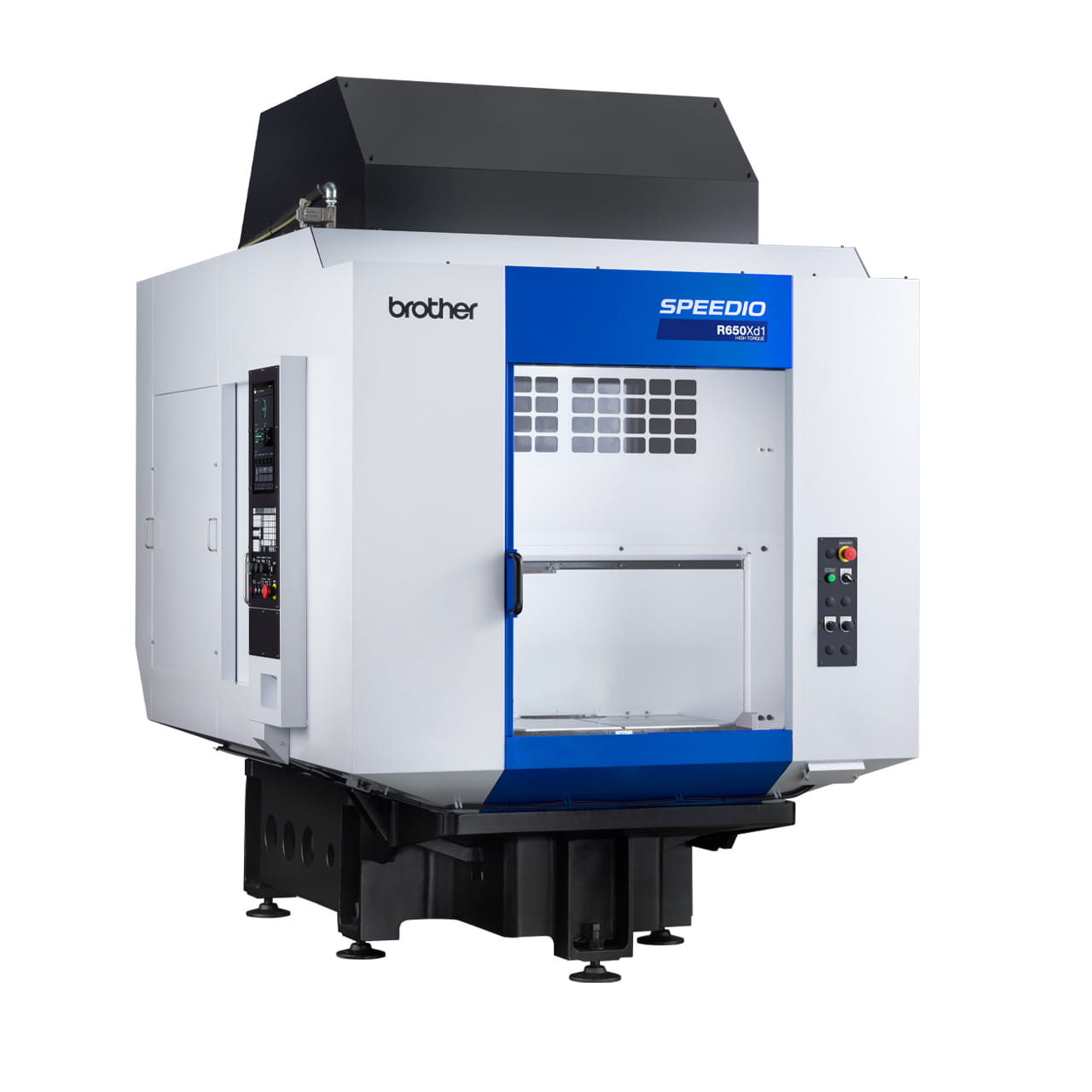
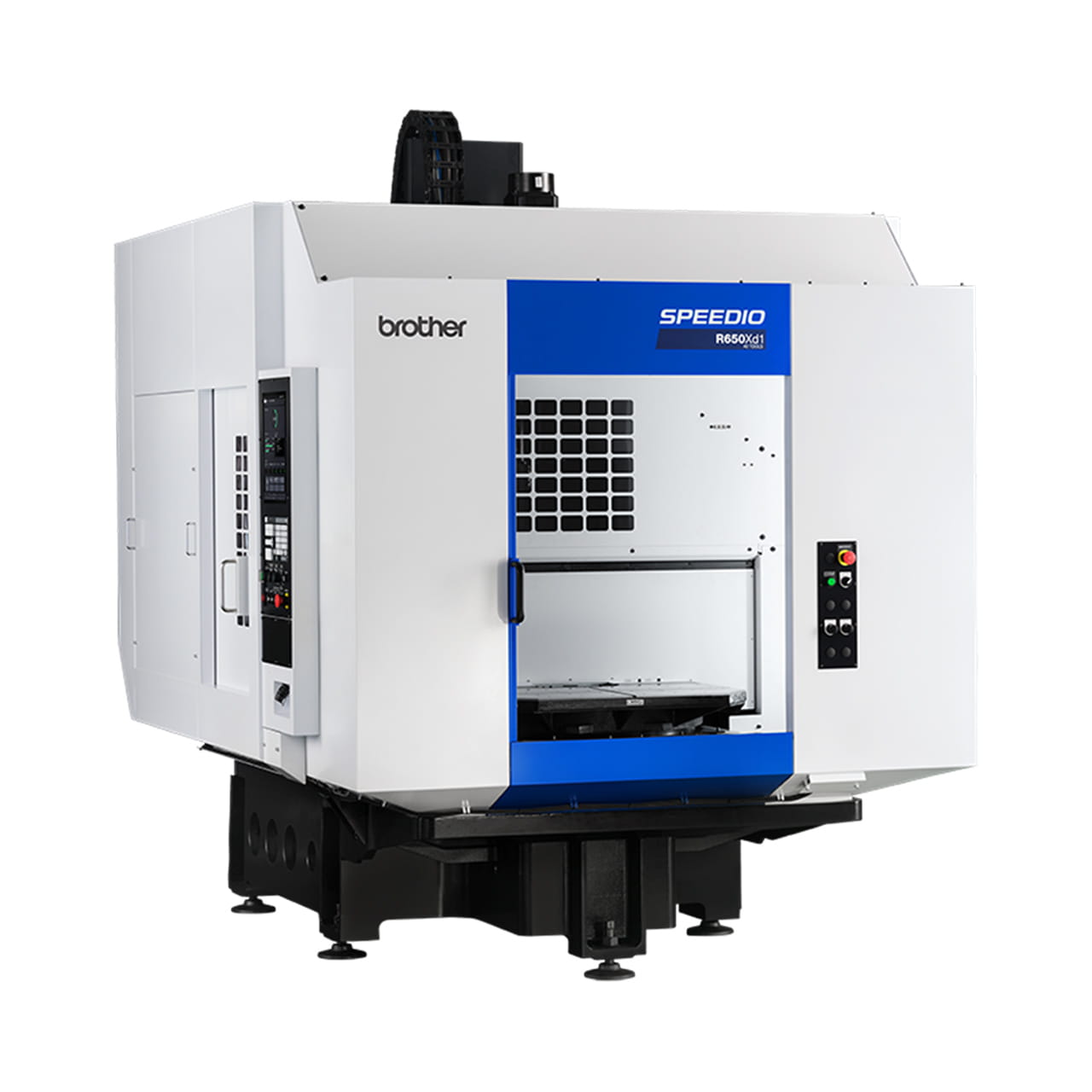
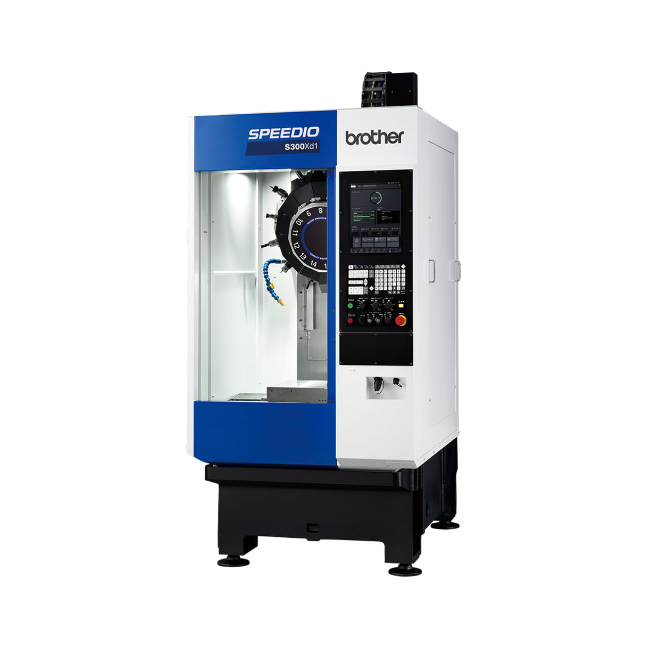
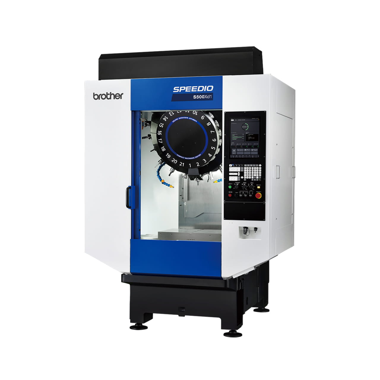
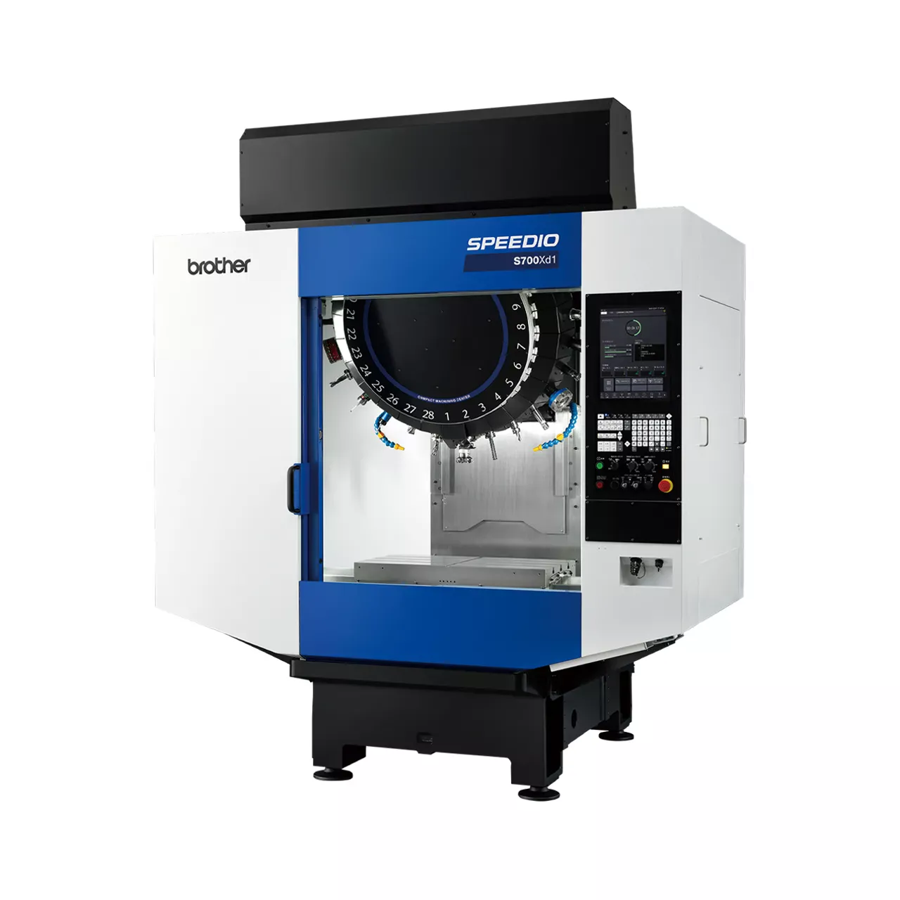
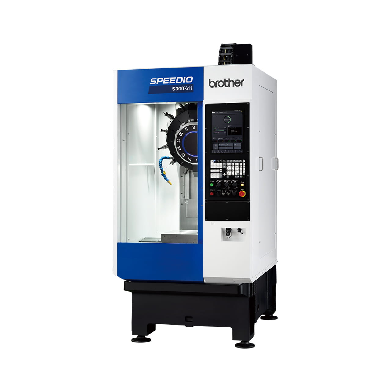
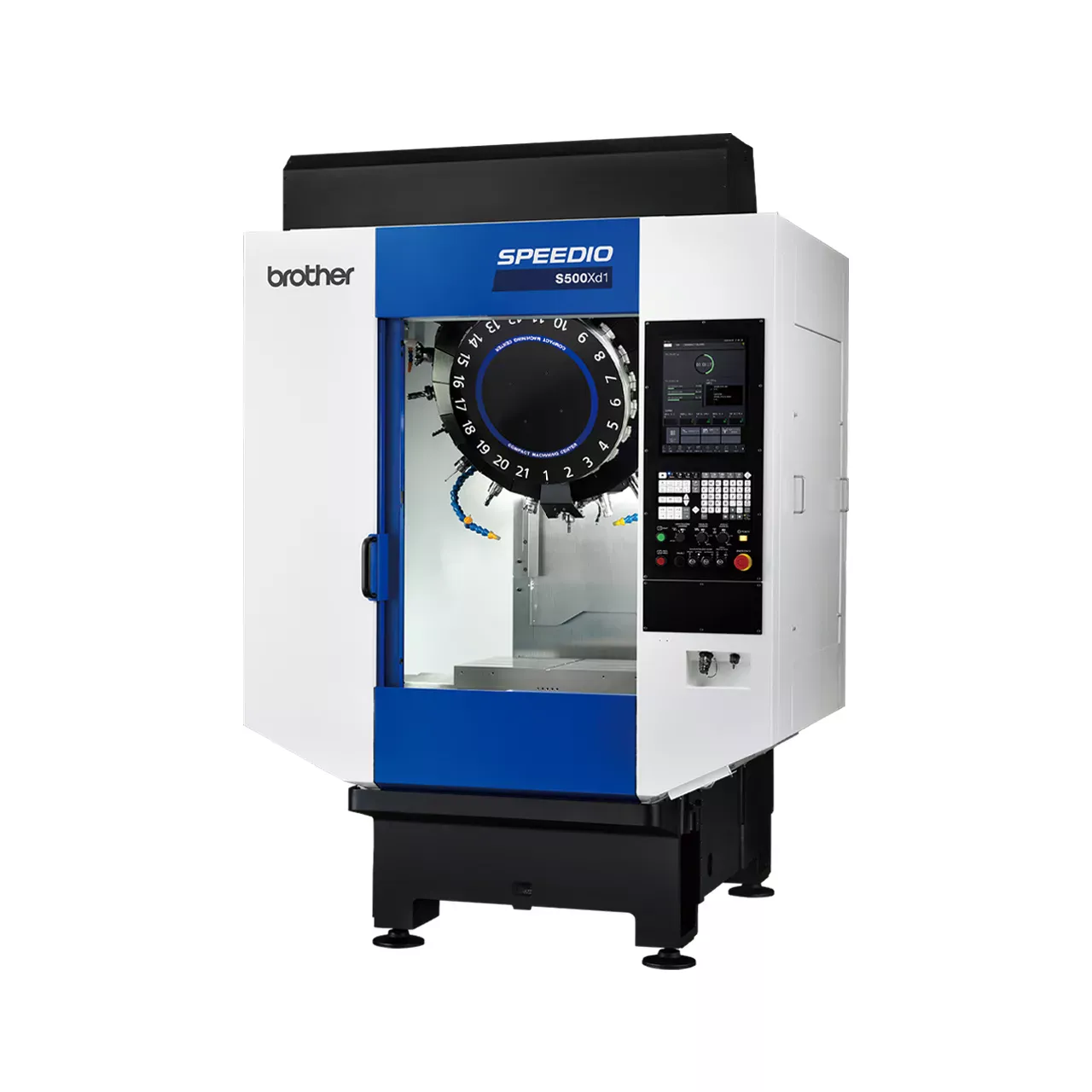
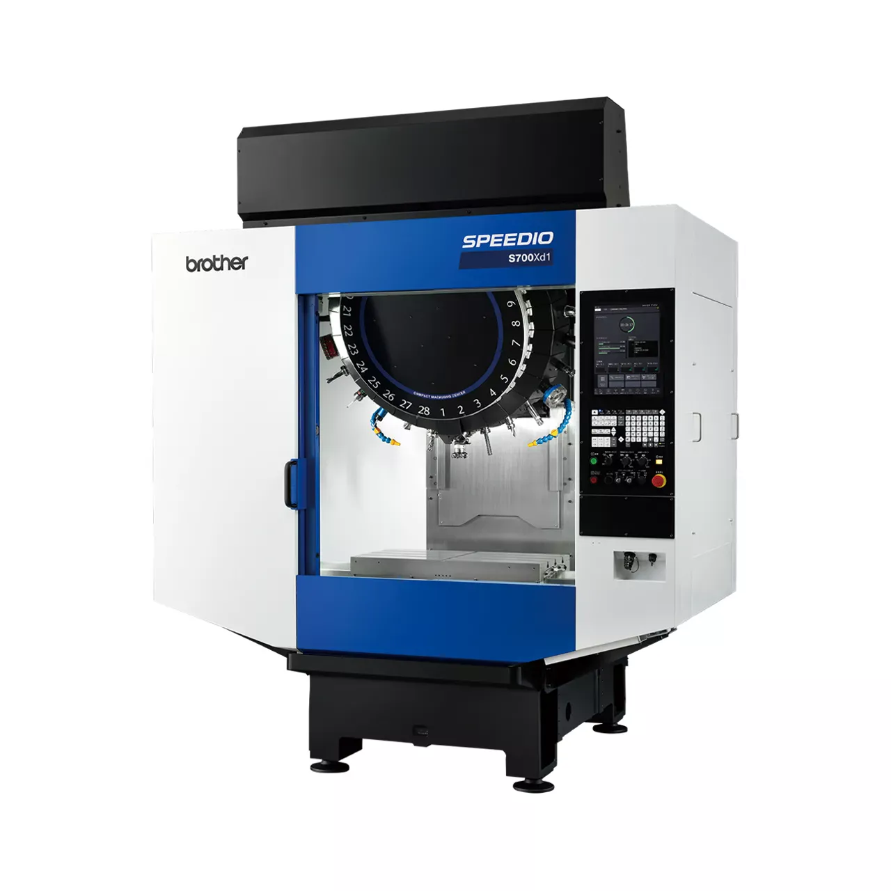
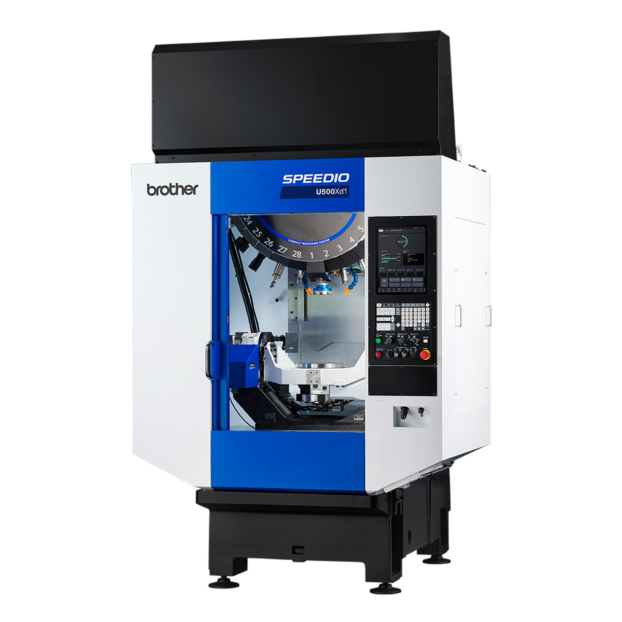
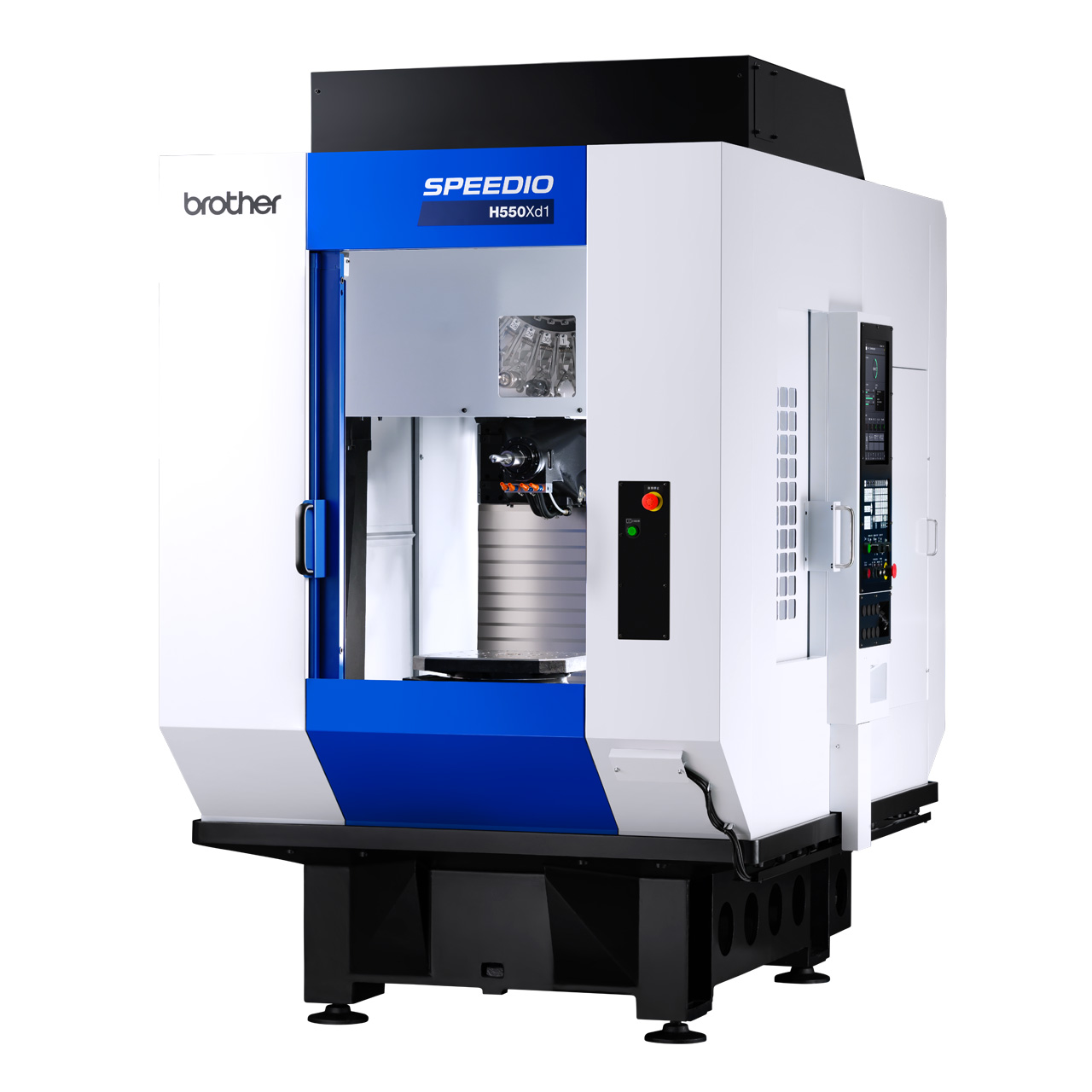
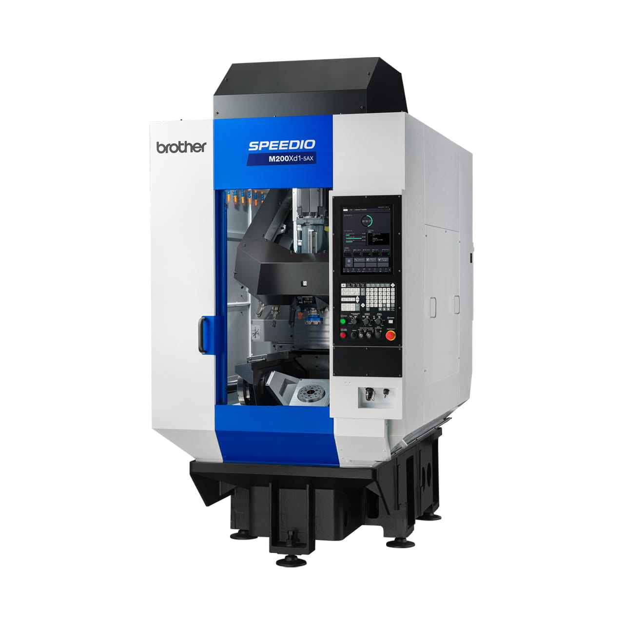
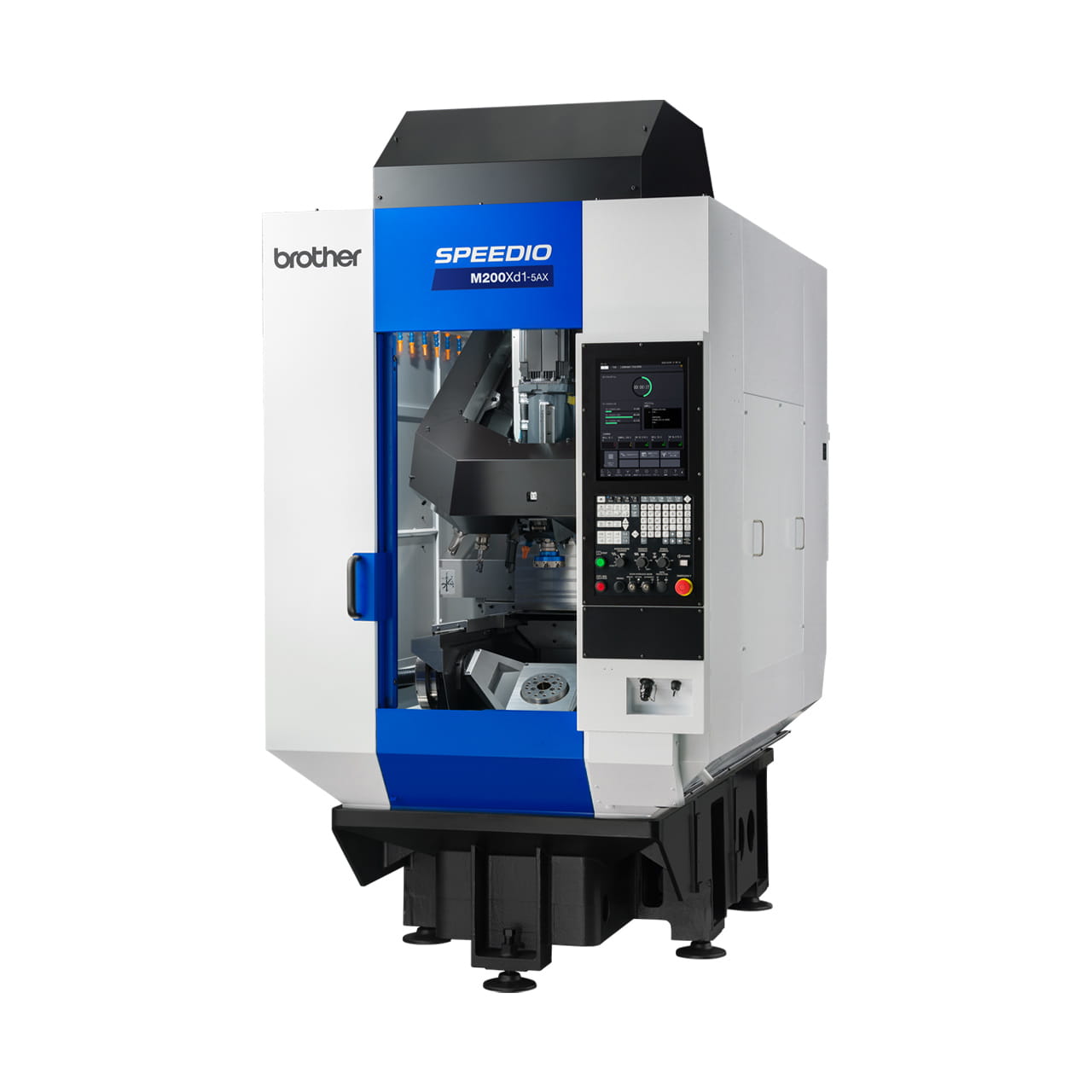
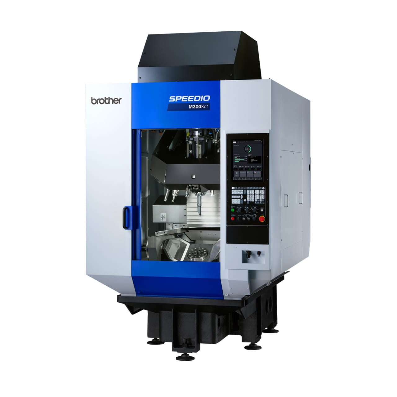
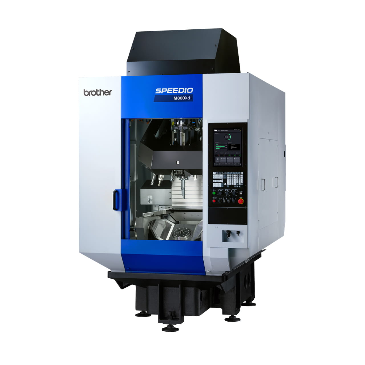
SPEEDIO F600X1
High Rigidity Compact Machining Center
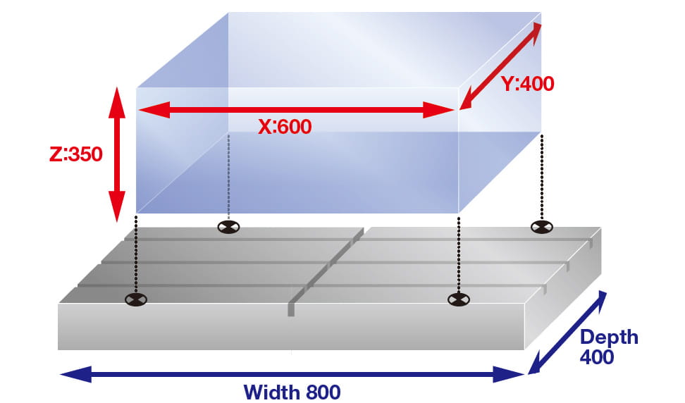
- Travels (mm): X: 600 Y: 400 Z: 350
- Max. spindle speed (min-1): 10,000 High-torque
- Tool storage capacity(pcs.): 14/ 22
New SPEEDIO Model High machining capabilities and stable machining have been achieved.
Information
Overview
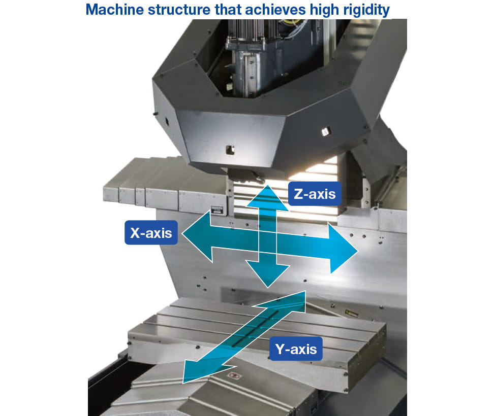
Highly rigid machine structure
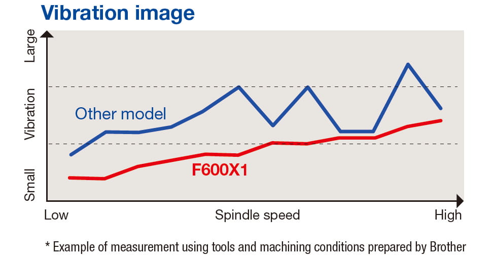
The machine structure has been reviewed from the basics, utilizing structural analysis techniques. Using optimal element components has enabled the machine to feature the highest rigidity in the SPEEDIO Series.
- Machine structure
The highest rigidity ever has been achieved by moving the table only by the Y-axis and using column movement for the X- and Z-axes, and reducing the spindle head overhang. - Highly rigid spindle
Spindle bearings larger than those of other models are used to improve spindle rigidity. - Highly rigid guide
Larger guides are used to improve the guide rigidity of each axis.
SPEEDIO's highest level machining capabilities
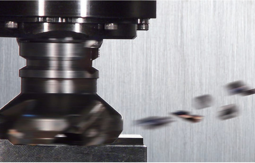
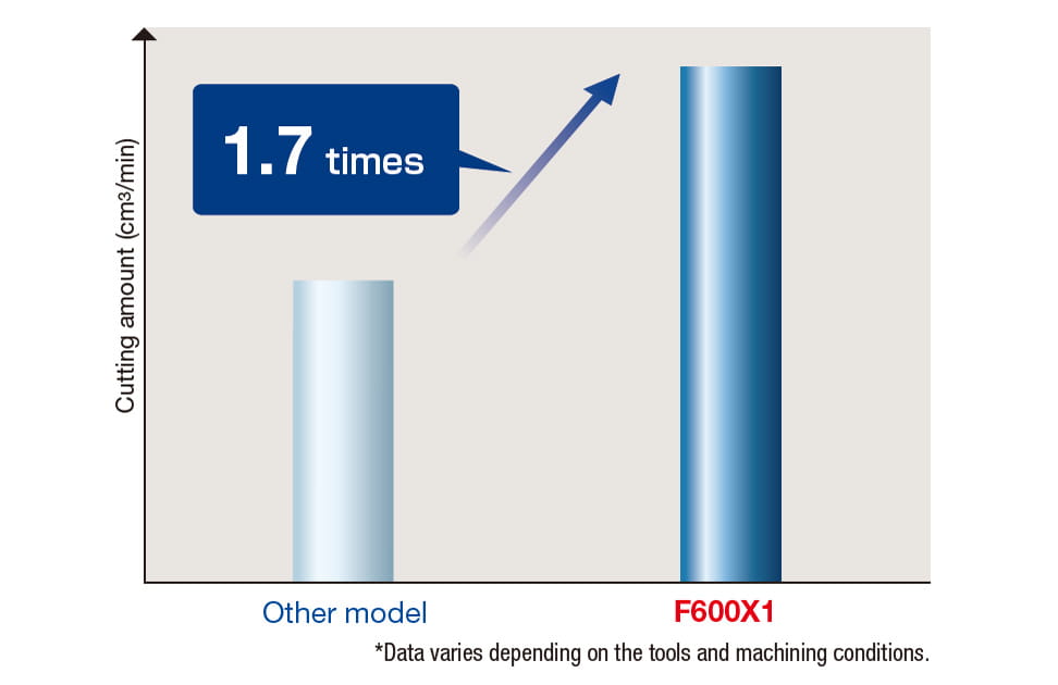
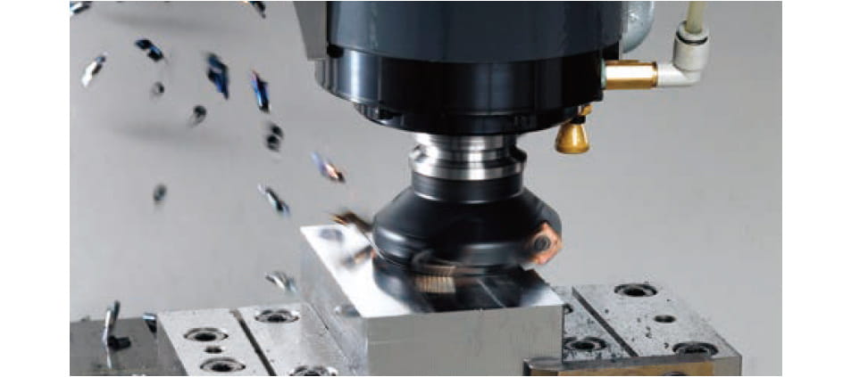
Cutting amount has significantly increased.
• Machining example : End mill ø16, Workpiece : Carbon steel
High-power spindle motor
The highest class high-torque motor among spindle motors used for #30 spindle machines is standard equipped.
Spindle motor characteristics
Max. torque (momentary) : 92Nm
Max. output : 26.2kW
Non-stop ATC
Fastest tool change has been achieved by optimizing and increasing the speed of the spindle start/stop, Z-axis up/down, and magazine operation.
22- tool magazine
Tool-Tool : 0.8s
Chip-Chip : 1.7s
14- tool magazine
Tool-Tool : 0.7s
Chip-Chip : 1.6s
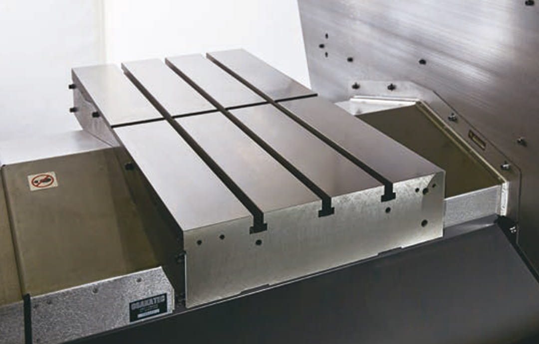
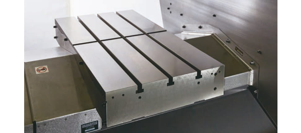
Table size and loading capacity
Size and loading capacity equivalent to high-end models.
Travels : X 600mm Y 400mm
Work area size : X:800mm Y:400mm
Max. loading capacity : 500kg
*The parameter must be changed.
High reliability
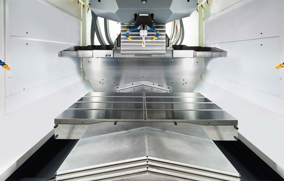
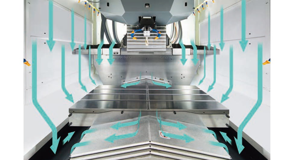
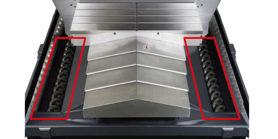
Chip discharge performance has been improved along with the expansion of the machining area. In addition, the machine is equipped with a variety of functions, such as air-assisted tool washing, to improve reliability.
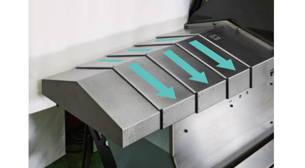
Roof-shape telescopic cover
Roof-shape telescopic covers are used for the X- and Y-axes to discharge chips rapidly.
NC unit
Equipped with tool monitoring functions
- ATC monitoring
- High-accuracy mode BII (read-ahead 200 blocks)
- Motor insulation resistance measurement function
- Waveform output to memory card
- PLC function
Specifications
Product Specification
F600X1
Max. spindle speed
10,000 High-torque
Travels
X: 600 Y: 400 Z: 350
Tool storage capacity
14/ 22
Rapid traverse rate (XYZ-area)
50 x 50 x 50
Required Floor Space
1,800 x 2,654
BT dual contact spindle(BIG-PLUS)
Optional
Coolant Through Spindle(CTS)
Optional
| item | F600X1 *9 | ||
|---|---|---|---|
| CNC unit | CNC-C00 | ||
| Travels | X axis [mm (inch)] | 600 (23.6) | |
| Y axis [mm (inch)] | 400 (15.7) | ||
| Z axis [mm (inch)] | 350 (13.7) | ||
| Distance between table top and spindle nose end [mm (inch)] | 200 - 550 (7.8 - 21.6) | ||
| Table | Work area size [mm (inch)] | 800 x 400 (31.4 x 15.7) | |
| Max.loading capacity (uniform load) [kg (lbs)] | 400[881] (500[1,102])*6 | ||
| Spindle | Spindle speed [min-1] | 10,000min-1 high-torque specifications : 1 - 10,000 | |
| Speed during tapping [min-1] | MAX. 6,000 | ||
| Tapered hole | 7/24 tapered No.30 | ||
| BT dual contact system (BIG-PLUS) | Optional | ||
| Coolant Through Spindle (CTS) | Optional | ||
| Feed rate | Rapid traverse rate (XYZ-area) [m/min (inch/min)] | 50 x 50 x 50 (1,969 x 1,969 x 1,969) | |
| Cutting feed rate [mm/min (inch/min)] | X, Y, Z : 1 - 30,000 (0.04 - 1,181)*7 | ||
| ATC unit | Tool shank type | MAS-BT30 | |
| Pull stad type*4 | MAS-P30T-2 | ||
| Tool storage capacity [pcs.] | 14/22 | ||
| Max. tool length [mm (inch)] | 250 (9.8) | ||
| Max. tool diameter [mm (inch)] | 110(4.3)/125(4.9) No adjacent tool | ||
| Max. tool weight [kg (lbs)]*1 | 3.0 (6.6) (Total tool weight : 25 (55.1) for 14 tools, 40 (88.1) for 22 tools) | ||
| Tool selection method | Random shortcut method | ||
| Tool change time*5 | Tool To Tool : 0.7sec (14 tools), 0.8sec (22 tools)
Chip To Chip : 1.6sec (14 tools), 1.7sec (22 tools) |
||
| Electric motor | Main spindle motor (10 min/continuous) [kW]*2 | 10,000min-1 high-torque specifications : 12.8/9.2 | |
| Axis feed motor [kW] | X,Y : 1.0 Z : 1.8 | ||
| Power source | Power supply | AC 200 to 230 V±10%, 3-phase, 50/60Hz±2% | |
| Power capacity (continuous) [kVA] | 10,000min-1 high-torque specifications : 10.4 | ||
| Air supply | Regular air pressure [MPa] | 0.4 - 0.6 (recommended value : 0.5MPa)*8 | |
| Required flow [L/min] | 45 | ||
| Machine dimensions | Height [mm (inch)] | 2,750 (108.2) | |
| Required floor space (with control unit door open) [mm (inch)] | 1,800 x 2,465 [3,162] (70.9 x 97.0 [124.5]) | ||
| Weight (including control unit, machine cover) [kg (lbs)] | 3,600 (7,937) | ||
| Accuracy*3 | Accuracy of bidirectional axis positioning (ISO230-2:2006) [mm (inch)] | 0.006 - 0.020 (0.00024 - 0.00079) | |
| Repeatability of bidirectional axis positioning (ISO230-2:2006) [mm (inch)] | Less than 0.004 (0.00016) | ||
| Front door | 2doors | ||
| Standard accessories | Instruction Manual (1 set), anchor bolts (4 pcs.), leveling bolts (4 pcs.), machine cover (manual door) | ||
- *1 Actual tool weight differs depending on the configuration and center of gravity.The figures shown here are for reference only.
- *2 Spindle motor output differs depending on the spindle speed.
- *3 Measured in compliance with ISO standards and Brother standards.
- *4 Brother specifications apply to the pull studs for CTS.
- *5 Measured in compliance with JIS B6336-9 and MAS011-1987.
- *6 Acceleration must be adjusted for Y axis.
- *7 When high accuracy mode B is used (When not used, 1 - 10,000 mm/min for X/Y axes and 1 - 20,000 mm/min for Z axis).
- *8 Regular air pressure varies depending on the machine specifications, machining program details, or use of peripheral equipment. Set the pressure higher than the recommended value.
- *9 The machine needs to be equipped with a relocation detection device depending on the destination. Machines equipped with a relocation detection device come with “RD” at the end of the model name.
| CNC model | CNC-C00 | |
|---|---|---|
| Control axes | 5axes ( X, Y, Z, additional axes) | |
| Simultaneously controlled axes | Positioning | 5 axes (X, Y, Z, A, B) |
| Interpolation |
|
|
| Least input increment | 0.001 mm, 0.0001 inch, 0.001 deg. | |
| Max.programmable dimension | ±9999.999mm, ±999.9999inch | |
| Display | 12.1-inch color LCD | |
| Memory capacity | Approx.100 Mbytes (Total capacity of program and data bank) | |
| External communication | USB memory interface, Ethernet, RS232C (Optional) | |
| No.of registrable programs | 4,000 (Total capacity of program and data bank) | |
| Program format | NC language, conversation (changed by parameter), conversion from conversation program to NC language program available |
|
| Standard NC functions |
|
|
| Optional NC functions |
|
|
- *1 Measuring instrument needs to be prepared by users.
- *2 When the submicron command is used, changing to the conversation program is disabled.
- *3 Minute block processing time can be changed. As there are some restrictions, please contact your local distributor for details.
- * "Control axes" and "Simultaneously controlled axes" indicate the maximum number of axes. These are different depending on the destination or specifications.
- * Ethernet is a trademark or registered trademark of XEROX in the United States.
- * Functions listed under (NC) and (Conversation) are available only for NC programs and conversation programs respectively.
For options, please contact us.


