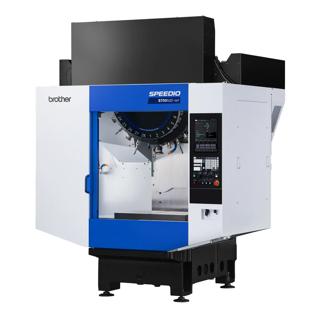
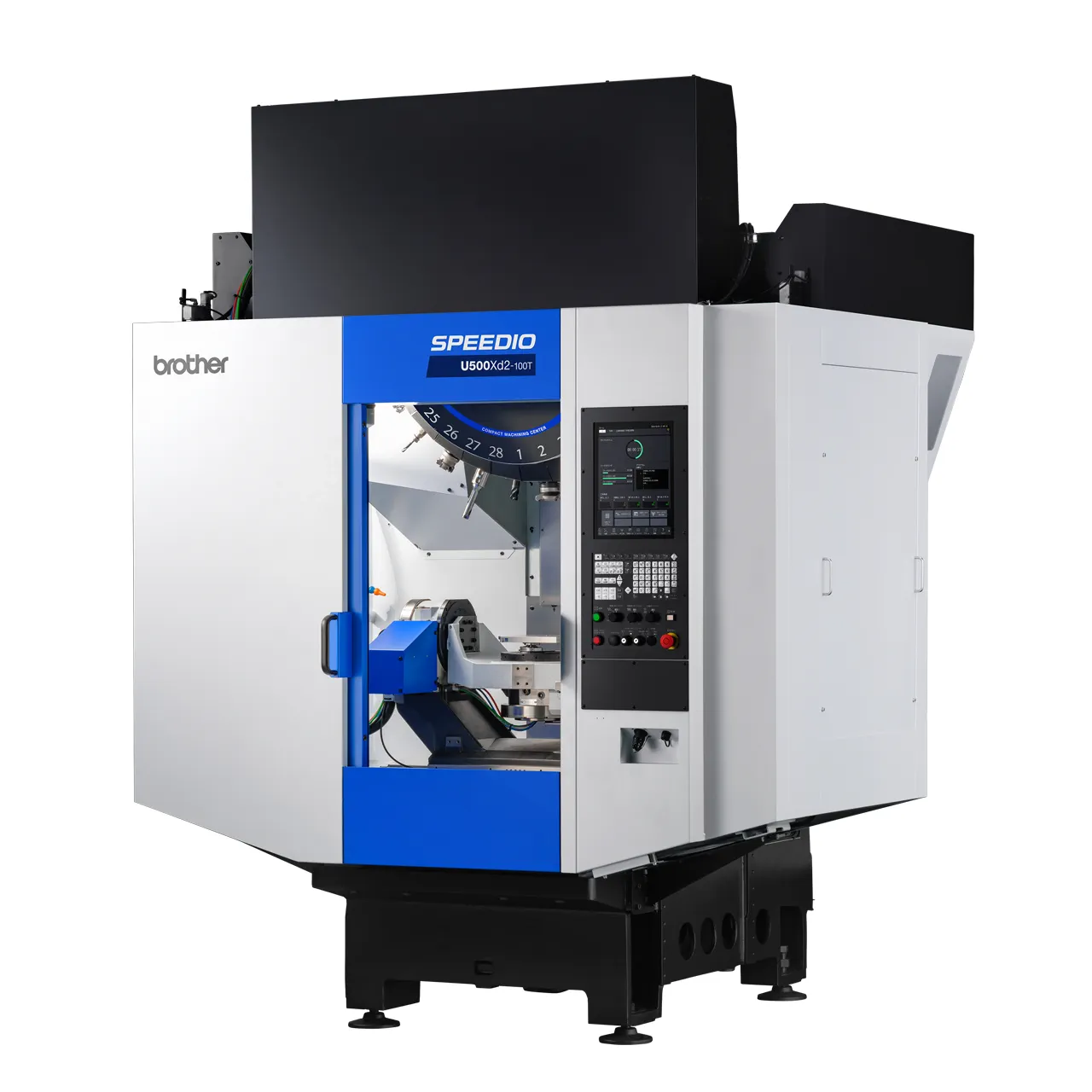
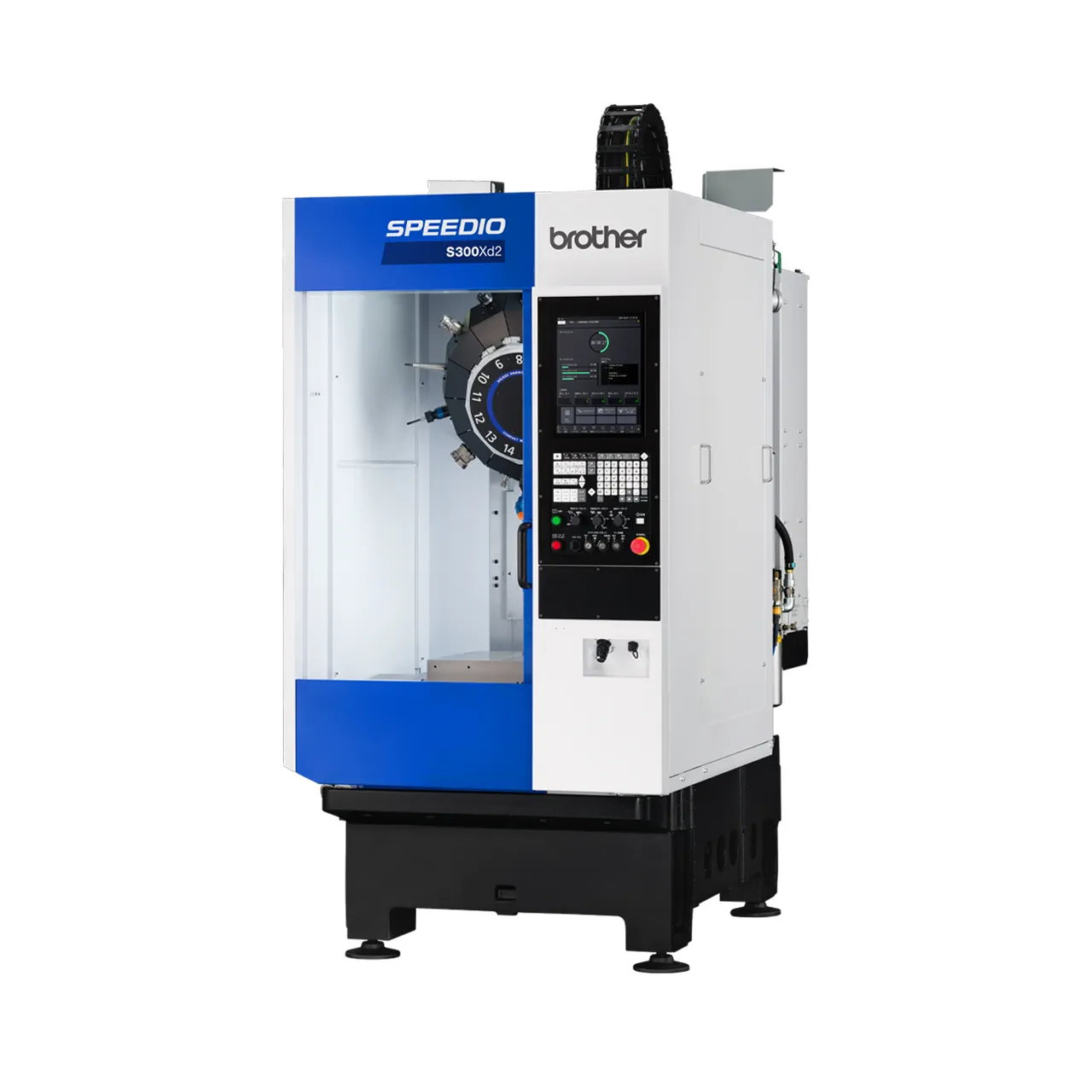
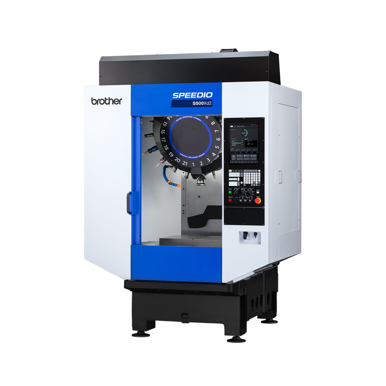
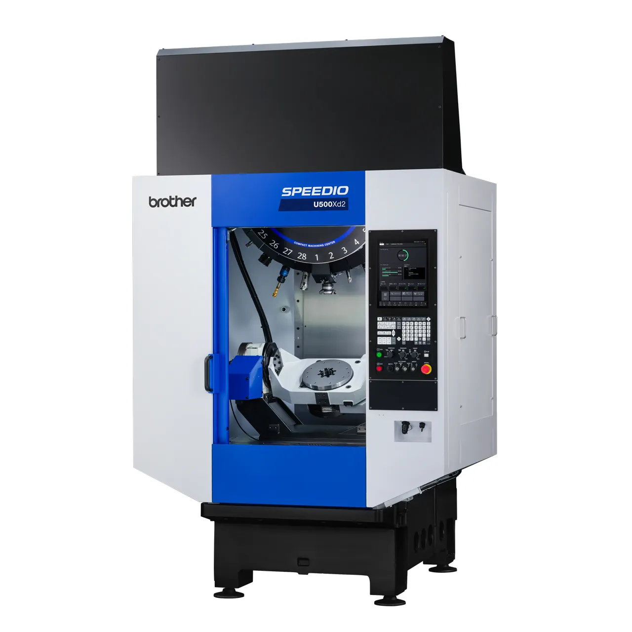
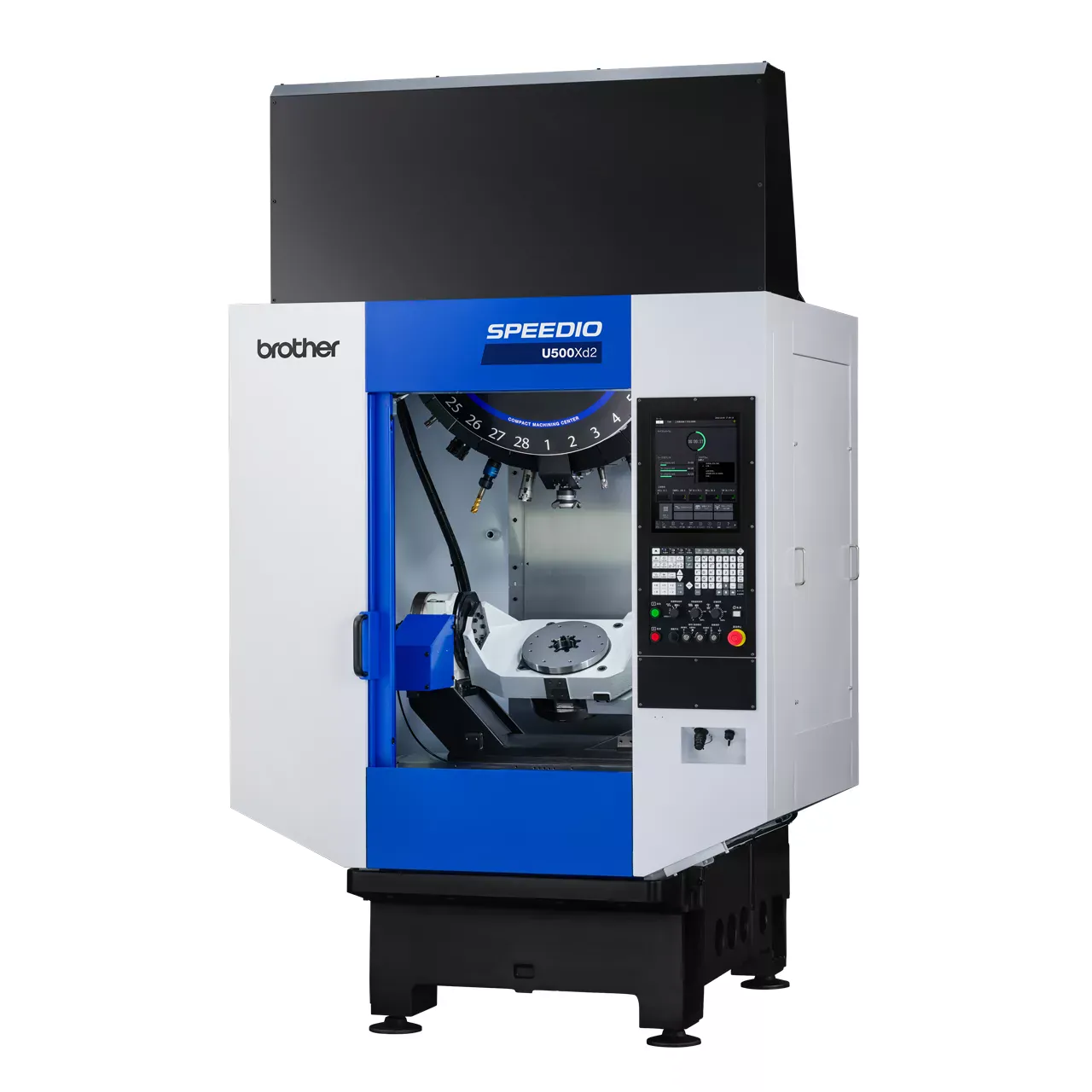
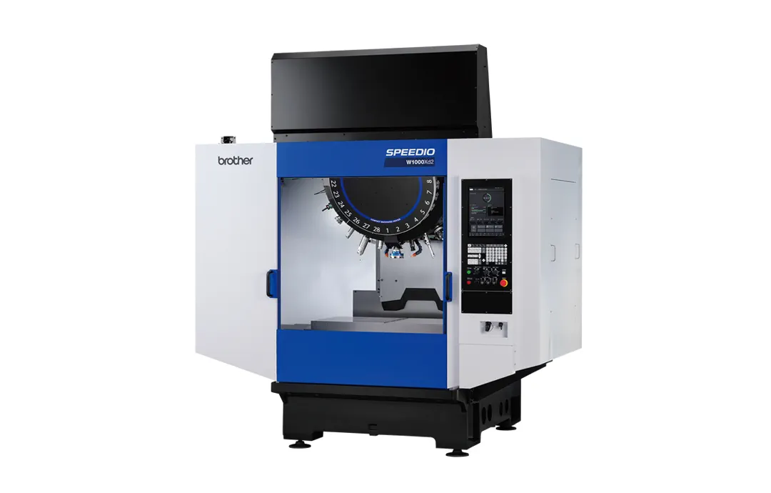
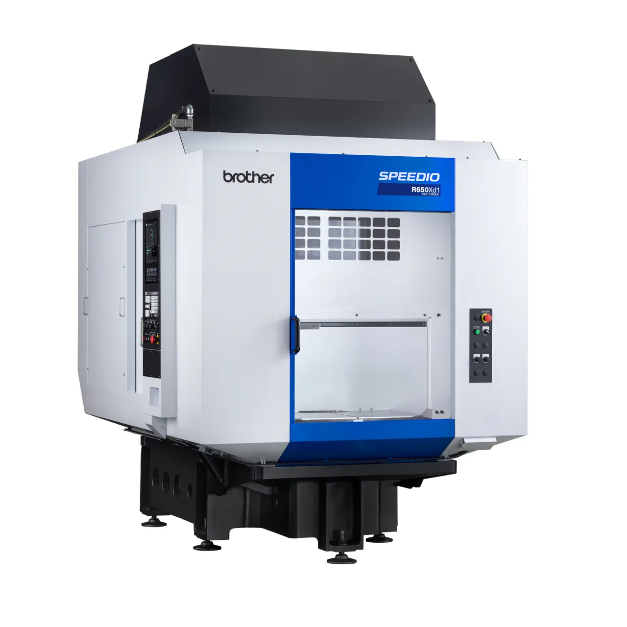
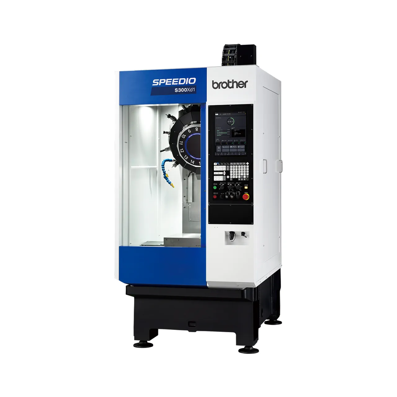
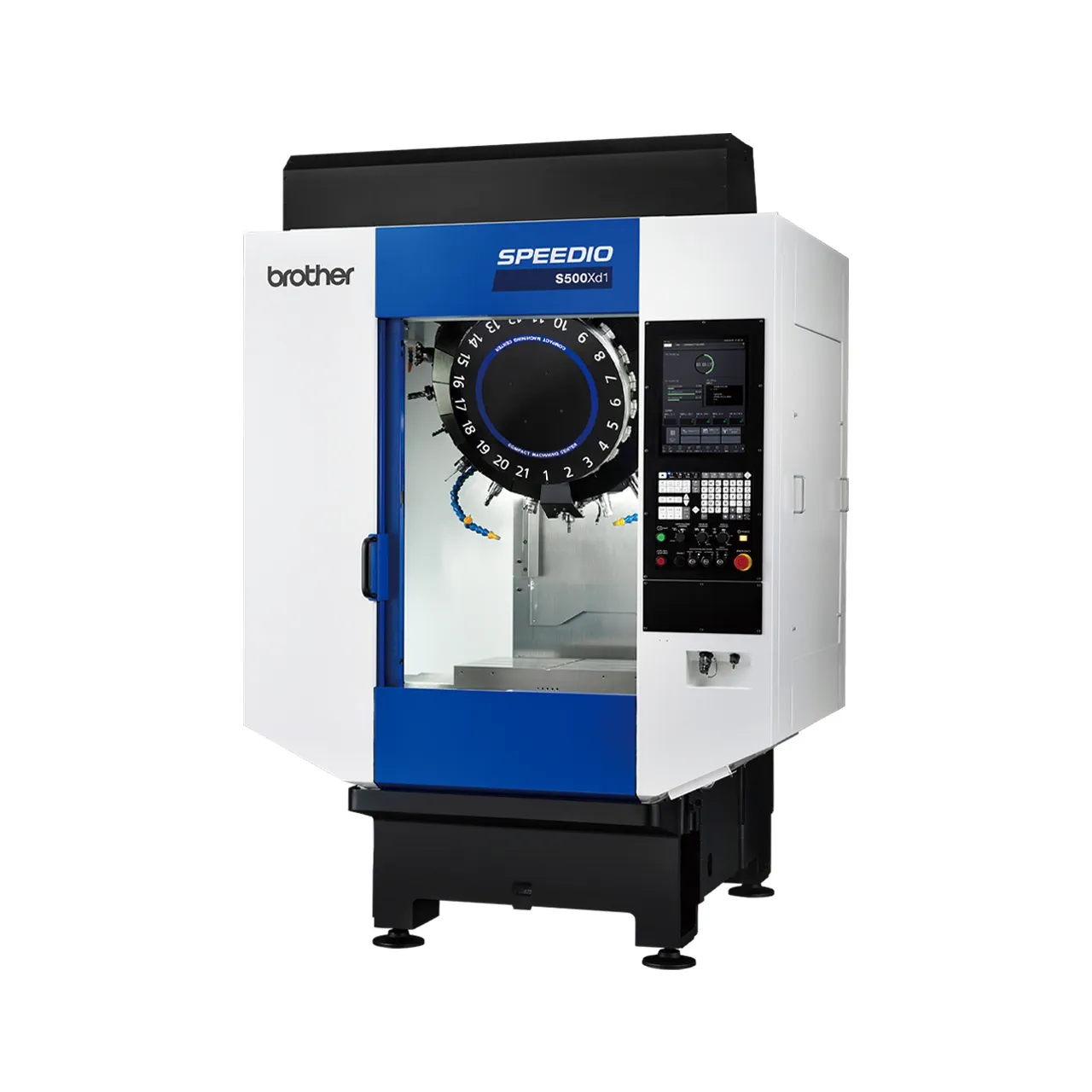
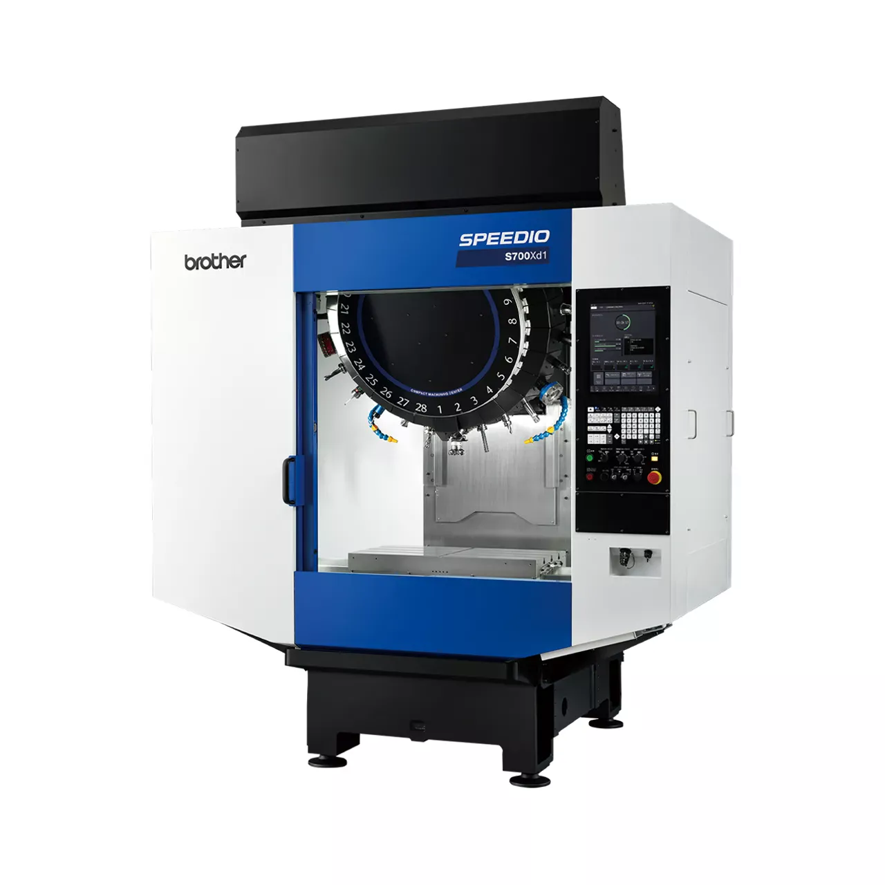
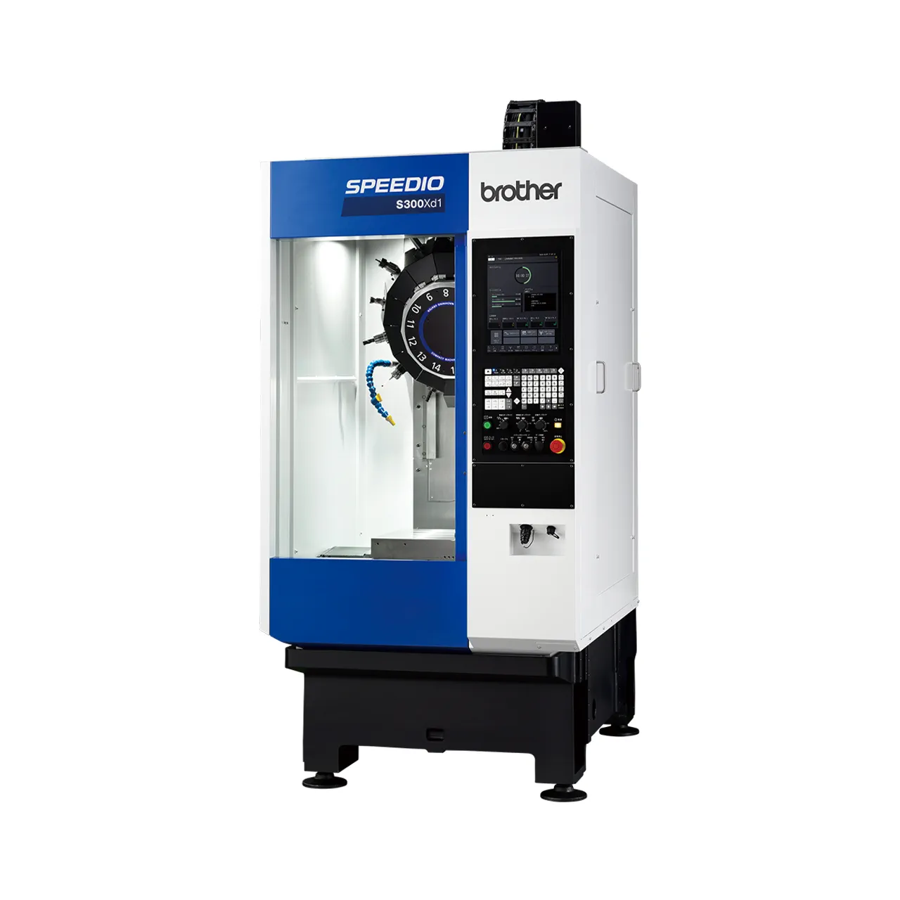
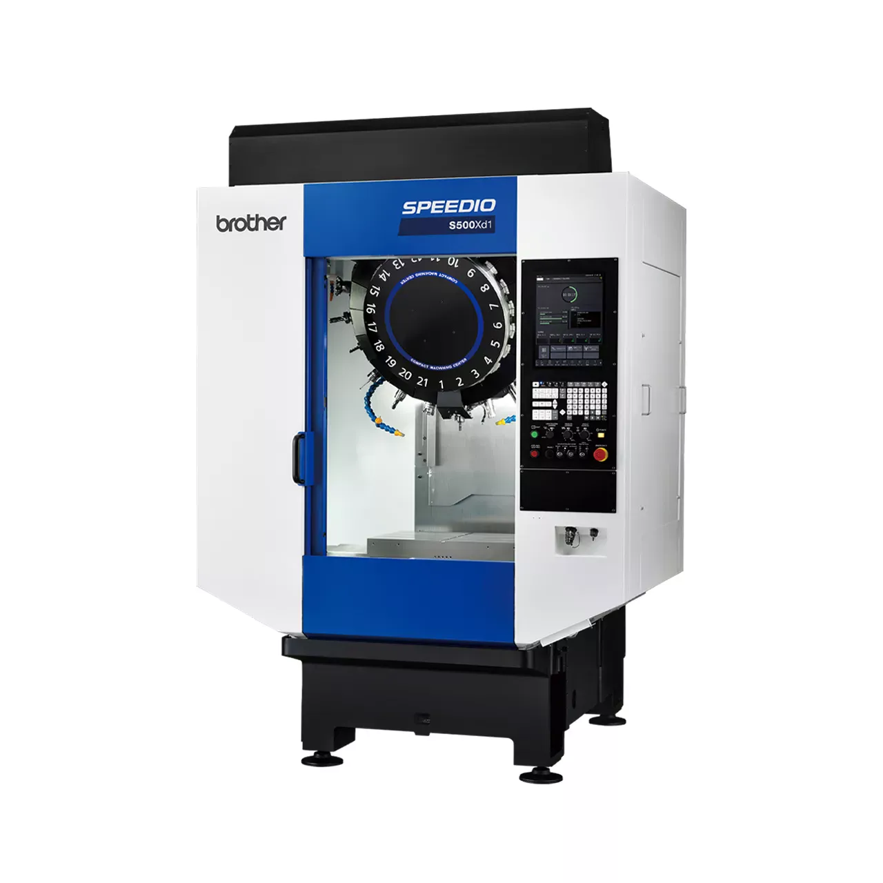
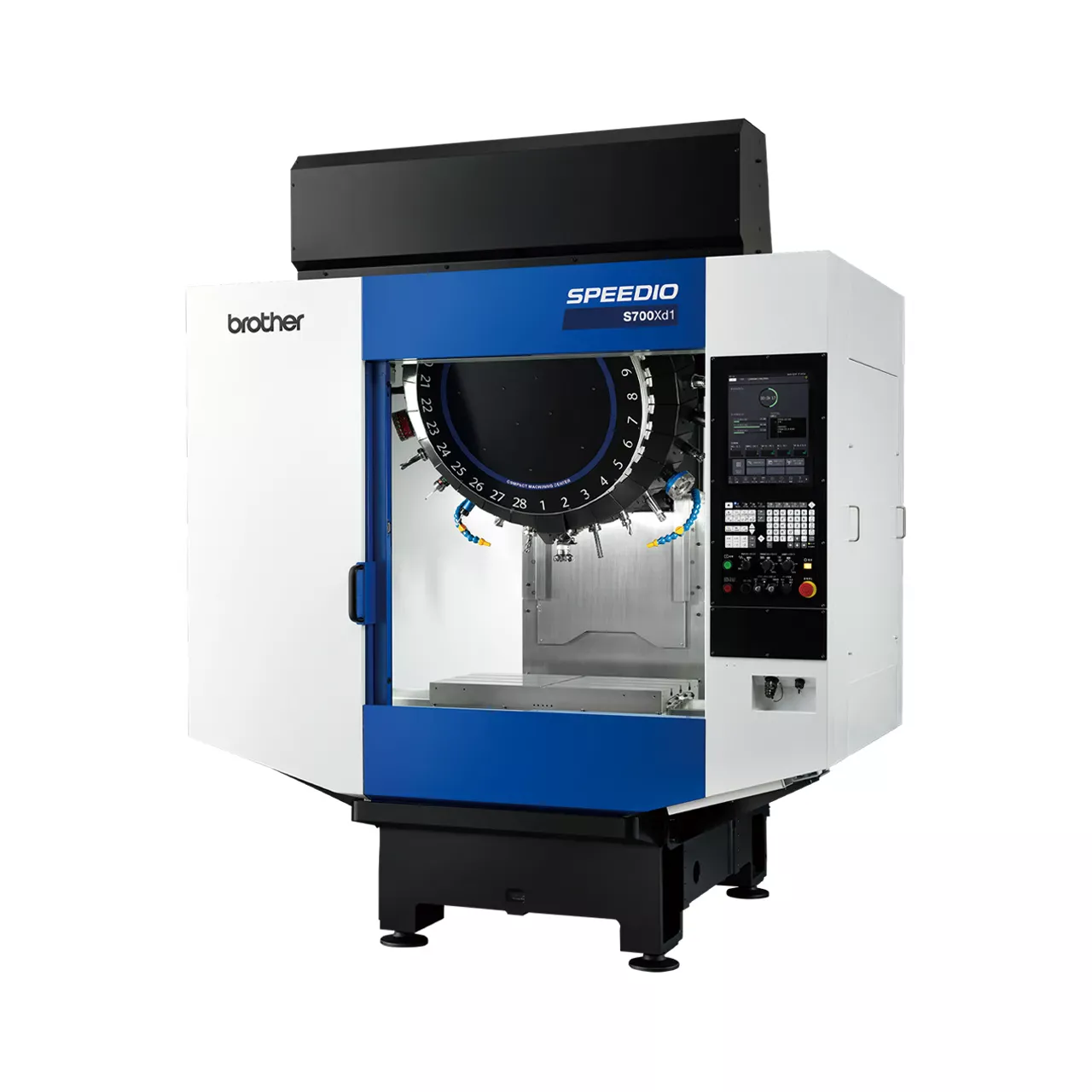
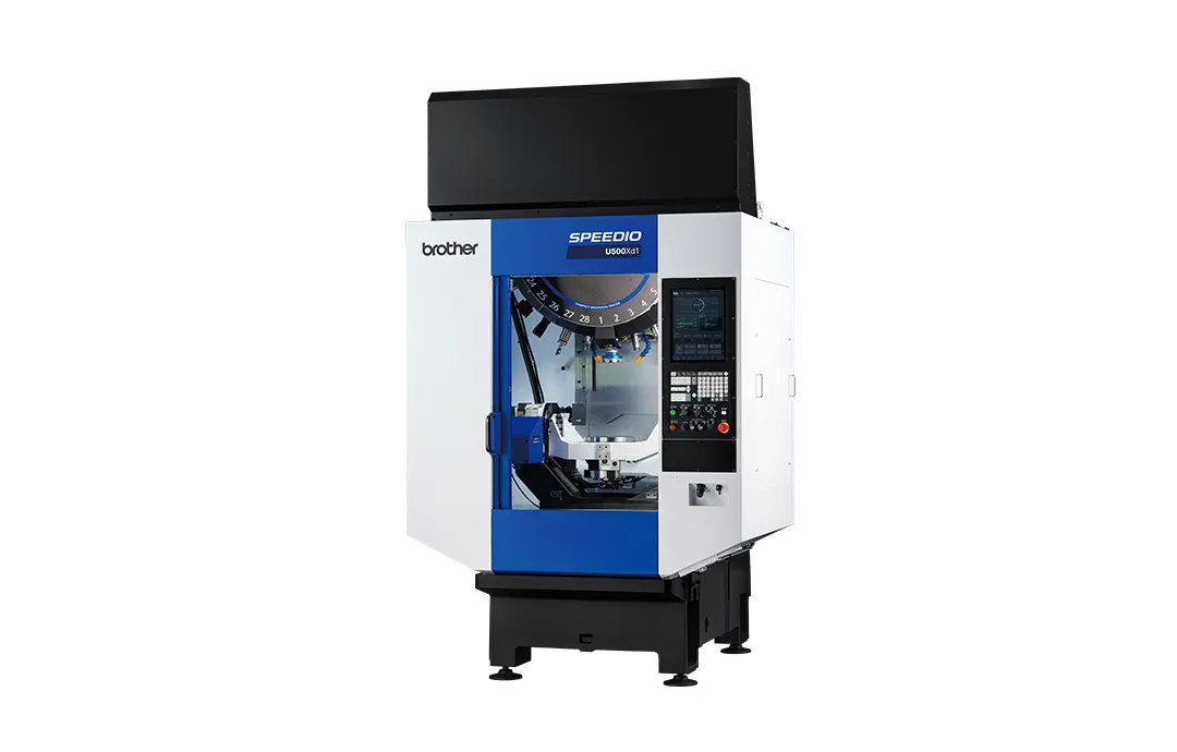
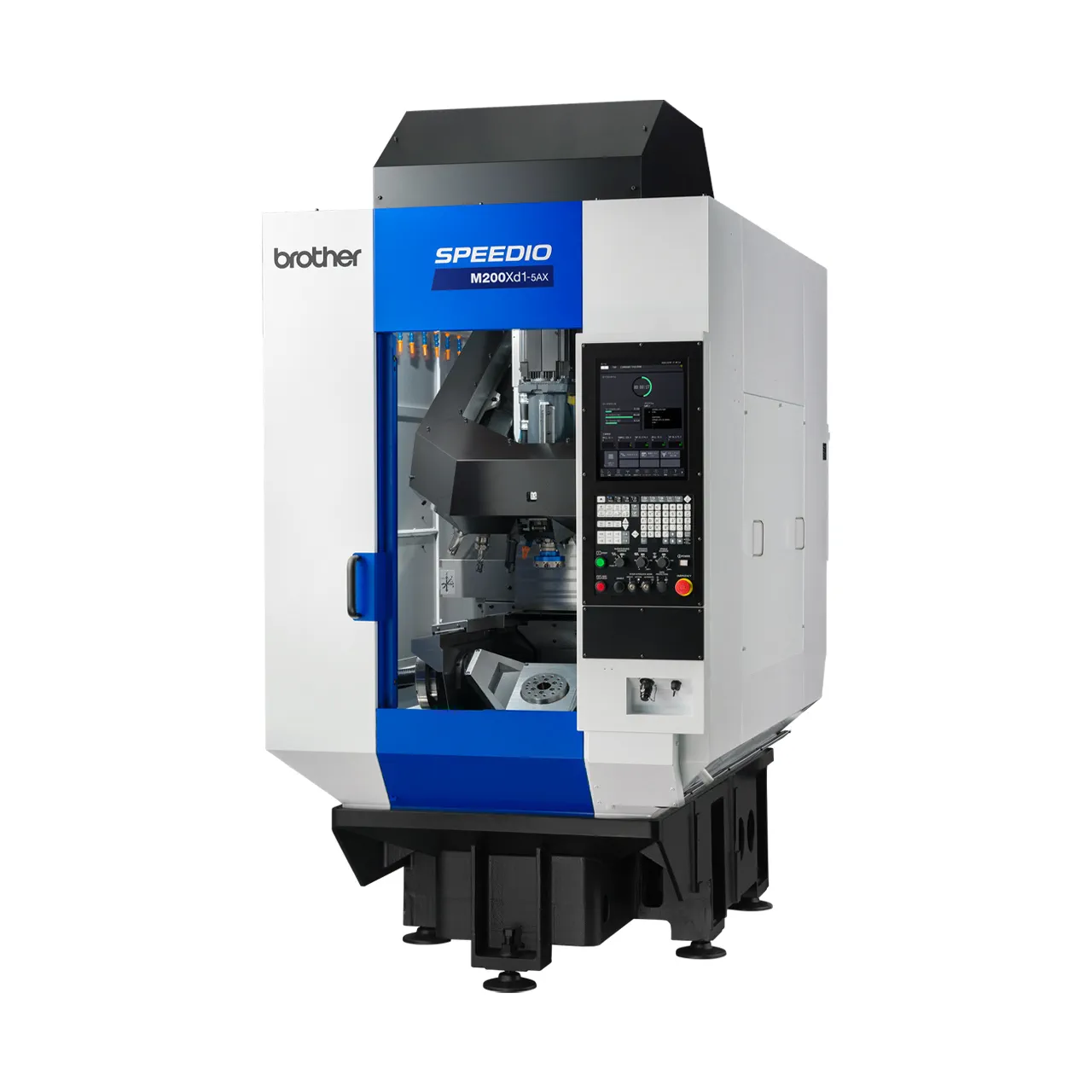
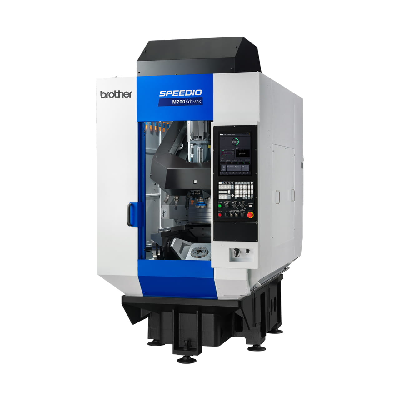
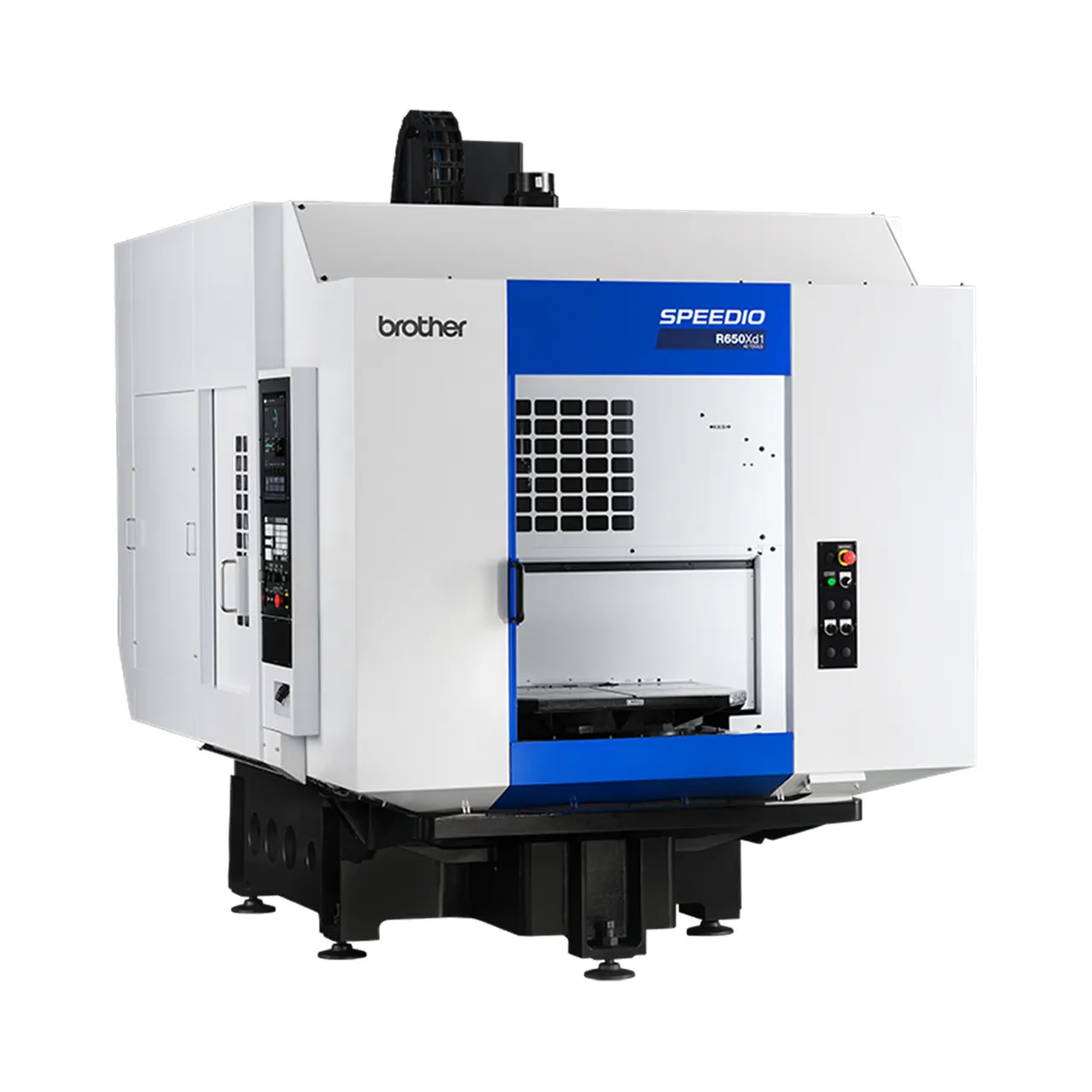
SPEEDIO R650Xd1 40tools
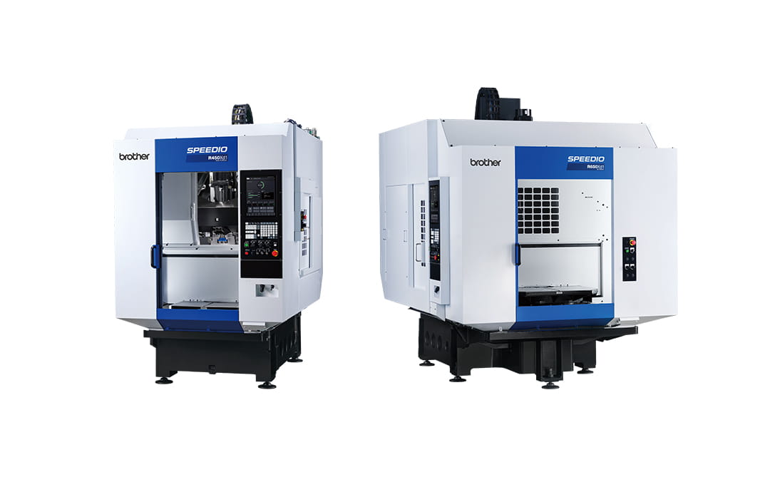
Pallet Changing Compact Machining Center
- Travels (mm): X: 650 Y: 400 Z: 435
- Max. spindle speed (min-1): 10,000/ (Optional) 16,000/ (Optional) 10,000 high-torque
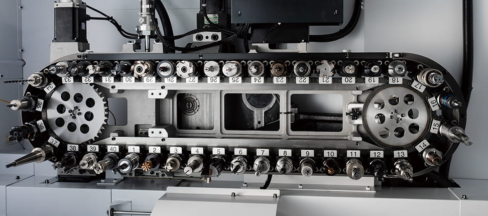
- Tool storage capacity(pcs.): 40
Select variants: R650Xd1 40tools
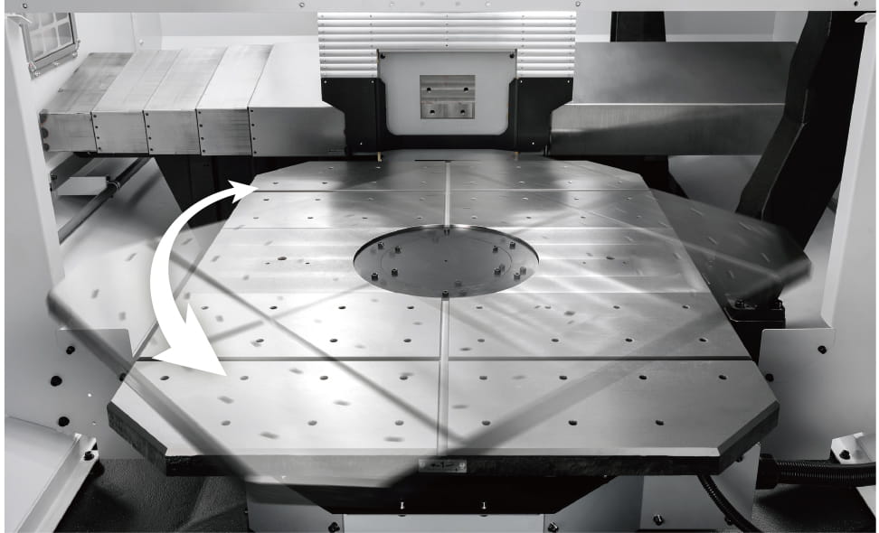
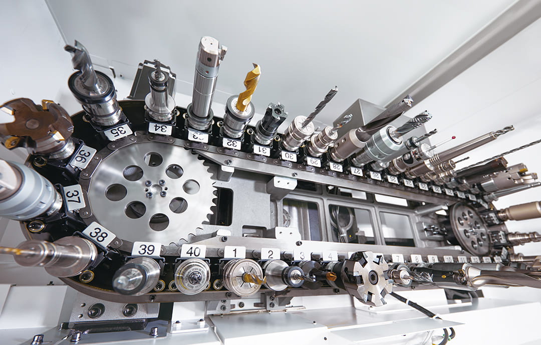
Equipped with a "QT table", Brother's original pallet changer that avoids lift-up motion, new CNC, and tool magazine with up to 40-tool capacity to improve productivity at every production site.
Information
Overview
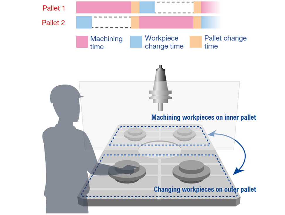
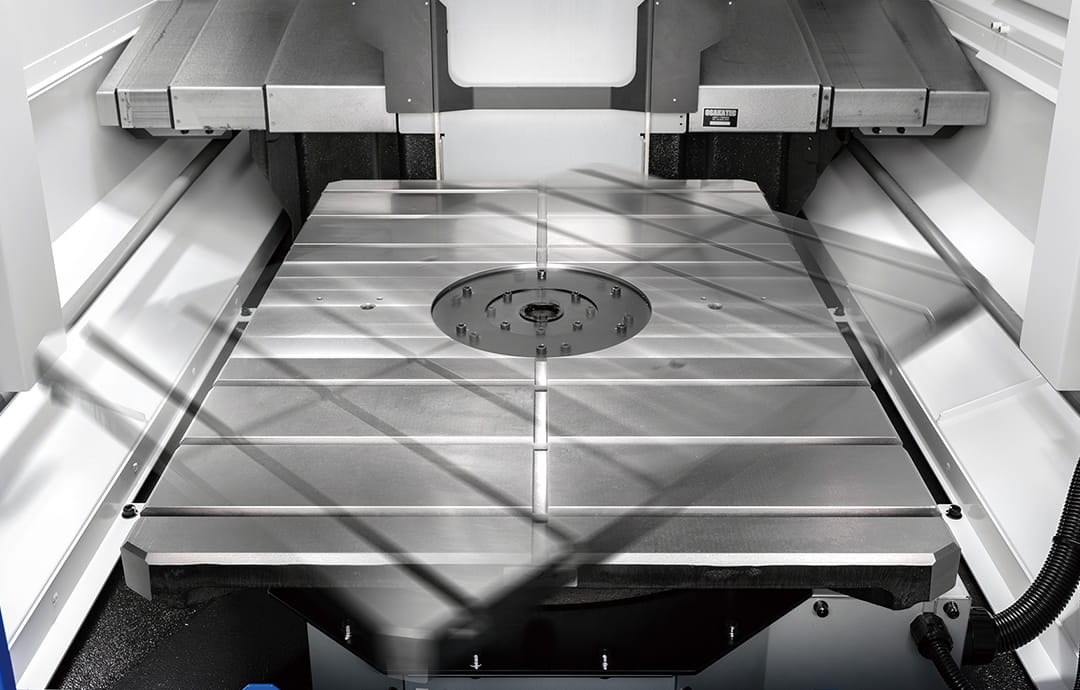
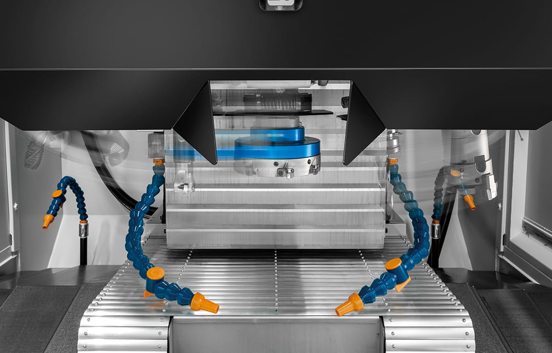
With a wide jig area and a high degree of reliability, the QT table enables non-stop machining to achieve high productivity.
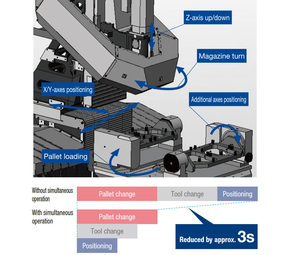
Optimized acceleration/deceleration control achieves much faster pallet change.
Pallet change time
R450Xd1: 2.9 s → 2.7 s
R650Xd1: 3.4 s → 3.1 s
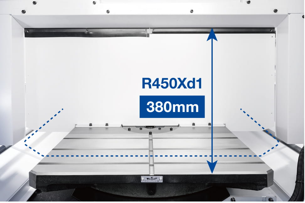
Max. jig height
R450Xd1: 350 → 380
R650Xd1: 420 → 450
Overwhelming high productivity is achieved by utilizing advantages of machine/controller integrated development, including optimized and faster simultaneous operation and tool change operation.
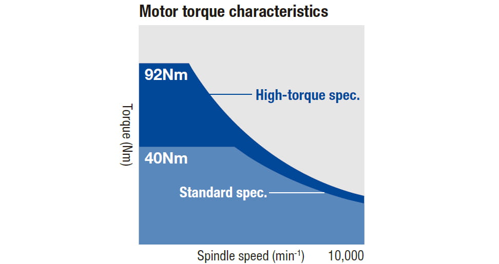
High-torque spec. (optional)
Max. torque : 92Nm
Max. output : 26.2kW
Standard spec.
Max. torque : 40Nm
Max. output : 18.9kW
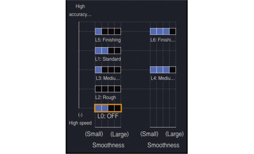
Simple setting for high accuracy mode
Machining accuracy/surface quality parameters can be adjusted by simple operation. This helps achieve high-quality machining easily.
High accuracy mode BI : Look-ahead 160 blocks
High accuracy mode BII (optional) : Look-ahead 1000 blocks
Specifications
Product Specification
R650Xd1 40tools
Max. spindle speed [min⁻¹]
10,000/ (Optional) 16,000/ (Optional) 10,000 high-torque
Travels [mm (inch)]
X: 650 Y: 400 Z: 435
Tool storage capacity [pcs.]
40
Rapid traverse rate (XYZ axes) [m/min (inch/min)]
50 x 50 x 50
Required floor space [mm (inch)]
2,145 x 3,029
BT dual contact spindle(BIG-PLUS)
Optional
Coolant Through Spindle(CTS)
Optional
Low table
Optional
| item | R450Xd1 / R450Xd1 RD *12 | R650Xd1 / R650Xd1 RD *12 14/22/28 tool magazine |
R650Xd1 / R650Xd1 RD *12 40-tool magazine |
||
|---|---|---|---|---|---|
| CNC unit | CNC-D00 | ||||
| Travels | X axis [mm (inch)] | 450 (17.7) | 650 (25.6) | ||
| Y axis [mm (inch)] | 320 (12.6) *7 | 400 (15.7) | |||
| Z axis [mm (inch)] | 305 (12.0) | 305 (12.0) | 435 (17.1) | ||
| Distance between table top and spindle nose end [mm (inch)] | 200-505 (7.9-19.9) [280-585 (11.0-23.0) *8 |
250-555 (9.8-21.8) [350-655 (13.8-25.8) *8] |
250-685 (9.8-27.0) [350-785 (13.8-30.9) *8] |
||
| Table | Work area size [mm (inch)] | One face 600 x 300 (23.6 x 11.8) |
One face 800 x 400 (31.5 x 15.7) | ||
| Max.loading capacity (uniform load) [kg (lbs)] |
One face 120 (265) [200 (441) *6] |
One face 200 (441) [300 (661) *6] |
|||
| Position time [sec.] | 2.7 *11 | 3.1 *11 | |||
| Spindle | Spindle speed [min-1] |
10,000min-1 specifications : 1 - 10,000 16,000min-1 specifications(Optional) : 1 - 16,000 10,000min-1 high-torque specifications(Optional) : 1 - 10,000 |
|||
| Speed during tapping [min-1] | MAX. 6,000 | ||||
| Tapered hole | 7/24 tapered No.30 | ||||
| BT dual contact system (BIG-PLUS) |
Optional | ||||
| Coolant Through Spindle (CTS) | Optional | ||||
| Feed rate | Rapid traverse rate (XYZ-area) [m/min (inch/min)] |
50 x 50 x 50 (1,969 x 1,969 x 1,969) | |||
| Cutting feed rate [mm/min (inch/min)] |
X, Y, Z axis: 1 - 30,000 (0.04 - 1,181) *9 | ||||
| ATC unit | Tool shank type | MAS-BT30 | |||
| Pull stud type *4 | MAS-P30T-2 | ||||
| Tool storage capacity [pcs.] | 14/22/28 | 14/22/28 | 40 | ||
| Max.tool length [mm (inch)] | 200 (7.9) | 200 (7.9) | 250 (9.8) | ||
| Max.tool diameter [mm (inch)] | 80 (3.1) | 80 (3.1) | 55 (2.1) / 125 (4.9) No adjacent tool |
||
| Max.tool weight [kg (lbs)] *1 | 3.0 (6.6) |
3.0 (6.6) |
4.0 (8.8) |
||
| Tool selection method | Random short cut method | Random short cut method | Double arm method (random closet path) |
||
| Tool change time *5 | Tool To Tool [sec.] | 0.6 / 0.7 (14-tool / 22 or 28 tool) |
0.6 / 0.8 (14-tool / 22 or 28 tool) |
0.9 | |
| Chip To Chip [sec.] | 1.3 / 1.5 (14-tool / 22 or 28 tool) |
1.4 / 1.5 (14-tool / 22 or 28 tool) |
2.5 | ||
| Electric motor | Main spindle motor (10 min/continuous)[kW] *2 |
10,000min-1 specifications : 10.1/7.0 16,000min-1 specifications(Optional) : 7.4/5.1 10,000min-1 high-torque specifications(Optional) : 12.8/9.2 |
|||
| Axis feed motor [kW] | X, Y axis : 1.0 , Z axis : 1.8 | ||||
| Power source | Power supply | AC 200 to 230 V±10%, 3-phase, 50/60Hz±2% | |||
| Power capacity (continuous) [kVA] | 10,000min-1 specifications : 9.5 16,000min-1 specifications(Optional) : 9.5 10,000min-1 high-torque specifications(Optional) : 10.4 | ||||
| Air supply | Regular air pressure [MPa] | 0.4 - 0.6 (recommended value: 0.5MPa *10) | |||
| Required flow [L/min] | 45 | 45 | 100 | ||
| Machine dimensions | Height [mm (inch)] | 2,584 (101.7) | 2,704 (106.5) | ||
| Required floor space *13 [with control unit door open] [mm (inch)] |
1,400 x 2,609 [3,448] (55.1 x 102.7 [135.7] ) |
1,830 x 3,029 [3,868] (72.0 x 119.3 [152.3] ) |
2,145 x 3,029 [3,868] (84.4 x 119.3 [152.3] ) |
||
| Weight (including control unit, machine cover) [kg (lbs)] | 2,750 (6,063) | 3,550 (7,826) | 4,150 (9,149) | ||
| Accuracy*3 | Accuracy of bidirectional axis positioning (ISO230-2:1988) [mm (inch)] | 0.006 - 0.020 (0.00024 - 0.00079) | |||
| Repeatability of bidirectional axis positioning (ISO230-2:2014) [mm (inch)] | Less than 0.004 (0.00016) | ||||
| Front door | 2doors | ||||
| Standard accessories | Instruction Manual (DVD 1 set), leveling bolts (4 pcs.) [R650Xd1: 5 pcs.], leveling plate (4 pcs.) [R650Xd1: 5 pcs.] |
||||
- *1 Actual tool weight differs depending on the configuration and center of gravity. The figures shown here are for reference only.
- *2 Spindle motor output differs depending on the spindle speed.
- *3 Measured in compliance with ISO standards and Brother standards. Please contact your local distributor for details.
- *4 Brother specifications apply to the pull studs for CTS.
- *5 Measured in compliance with JIS B6336-9 and MAS011-1987.
- *6 Can be increased up to R450Xd1: 200kg, R650Xd1: 300kg (one face) by changing the parameter. Please consult us separately.
- *7 When using the hydraulic rotary joint, the Y-axis travel becomes 290 mm.
- *8 Values when the low-floor table is selected.
- *9 When using high accuracy mode B.
- *10 Regular air pressure varies depending on the machine specifications, machining program details, or use of peripheral equipment. Set the pressure higher than the recommend value.
- *11 When table loading on one face is R450Xd1: 120kg, R650Xd1: 200kg.
- *12 The machine needs to be equipped with a relocation detection device depending on the destination. Machines equipped with a relocation detection device come with "RD" at the end of the model name.
- *13 The value does not include the coolant tank or chip conveyor.
- *14 When the turning diameter enlargement option is selected.
| Item | R450Xd1 | R650Xd1 |
|---|---|---|
| Type | 0 deg./180 deg. turntable system | 0 deg./180 deg. turntable system |
| Table dimension [mm (inch)] | One face 600 x 420 (23.6 x 16.5) | One face 800 x 535 (31.5 x 21.1) |
| Max. turning diameter [mm (inch)] | D1,020 (40.2) [D1,100 (43.3)] *14 | D1,250 (49.2) [D1,300 (51.2)] *14 |
| Max. jig height [mm (inch)] | 300 (11.8) [380 (15.0)] *8 | 350 (13.8) [450 (17.7)] *8 |
| Table work area size [mm (inch)] | One face 600 x 300 (23.6 x 11.8) | One face 800 x 400 (31.5 x 15.7) |
| Max. loading capacity [kg (lds)] | One face 120 (265) [200 (441)] *6 | One face 200 (441) [300 (661)] *6 |
| Rated table load inertia for turning axis [kg·m2] | One face 14.2 [23.5] *6 | One face 35.8 [53.7] *6 |
| Table turning system | AC servo motor(1kW) Worm gear (total speed reduction ratio:1/50) |
AC servo motor(0.82kW) Worm gear (total speed reduction ratio:1/60) |
| Table position time | 2.7 *11 | 3.1 *11 |
| Table change repeatability [mm (inch)] |
0.005 (0.0002) (in the X,Y, and Z axes directions 270(10.6) from the center of rotation) |
0.005 (0.0002) (in the X,Y, and Z axes directions 335(13.2) from the center of rotation) |
- * Quick Turn table is a turntable type 2-face pallet changer.
| CNC model | CNC-D00 | |
|---|---|---|
| Control axes | 7 axes (X, Y, Z, four additional axes) | |
| Simultaneously controlled axes | Positioning | 5 axes (X, Y, Z, A, B) |
| Interpolation | Linear : 4 axes (X, Y, Z, one additional axis) Circular : 2 axes Helical/Conical : 3 axes (X, Y, Z) |
|
| Least input increment | 0.001mm、0.0001inch、0.001 deg. | |
| Max.programmable dimension | ±999999.999mm、±99999.9999inch | |
| Display | 15-inch color LCD touch display | |
| Memory capacity | 500 Mbytes, 3 Gbytes (optional) (Total capacity of program and data bank) | |
| External communication | USB memory interface, Ethernet, RS232C (optional) | |
| No.of registrable programs | 4,000 (Total capacity of program and data bank) | |
| Program format | NC language, conversation (changed by parameter) Conversation from conversation program to NC language program available |
|
- * Number of "control axes" and/or "simultaneously controlled axes" are the maximum number of axes, which will differ depending on the destination country and the machine specifications.
- * Ethernet is a trademark or registered trademark of XEROX in the United States.
| Operation | Dry run Machine lock Program restart Rapid traverse override Cutting feed override Background editing Screen shot Operation level External input signal key
|
|---|---|
| Programming | Absolute / Incremental Inch / Metric Coordinate system setting Corner C / Corner R Rotational transformation Synchronized tap Subprogram Graphic display |
| Measurement | Automatic workpiece measurement *1 Tool length measurement |
| High speed and high accuracy | Machining parameter adjustment High-accuracy mode AIII High-accuracy mode BI (look-ahead 160 blocks) Backlash compensation
|
| Monitoring | Machining load monitoring ATC monitoring Overload prediction Waveform display / Waveform output to memory card Heat expansion compensation system ll (X, Y, and Z axes) Production performance display Tool life / Spare tool |
| Maintenance | Tap return function Status log Alarm log Operation log Motor insulation resistance measurement Tool washing filter with filter clogging detection Breake load test |
| Automatic / Network | Computer remote OPC UA Auto notification Built-in PLC (LD/ST/FBD)
|
| Energy saving | Automatic power off Standby mode Automatic coolant off Automatic work light off Chip shower off delay |
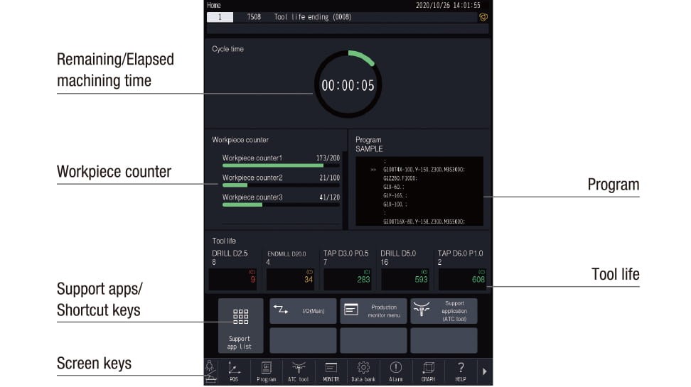
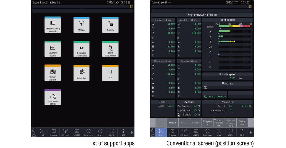
| Support apps | Adjust machine parameters ATC tool Tool life Waveform display Production performance Power consumption Recovery support Inspection PLC |
| Accessories | File viewer Notebook Calculator Register shortcut Display off |
| Functions limited to NC language | Menu programming Local coordinate system Expanded workpiece coordinate system One-way positioning Inverse time feed Programmable data input Tool length compensation Cutter compensation Scaling Mirror image External sub program call Macro Operation in tape mode Multiple skip function
|
| Functions limited to conversation | Operation program Schedule program Automatic tool selection Automatic cutting condition setting Automatic tool length compensation setting Automatic cutter compensation setting Automatic calculation of unknown number input Machining order control |
- *1 Measuring instrument needs to be prepared by users.
- *2 When the submicron command is used, changing to the conversation program is disabled.
- *3 There are restrictions on the axis configuration.
Example
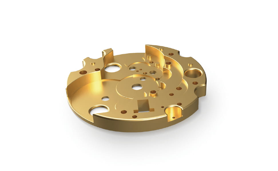
Brass
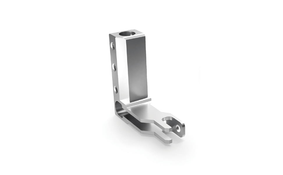
Stainless steel
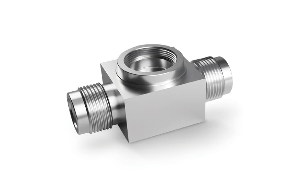
Stainless steel
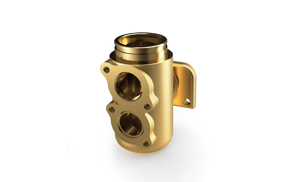
Brass
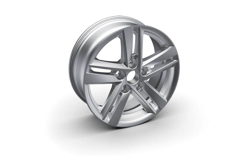
Aluminum alloy
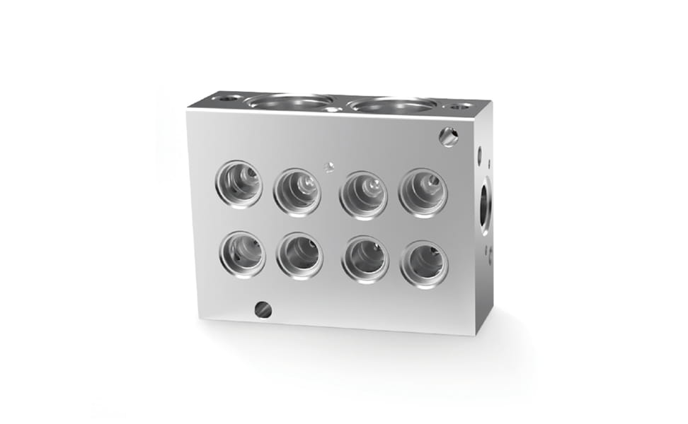
Aluminum alloy
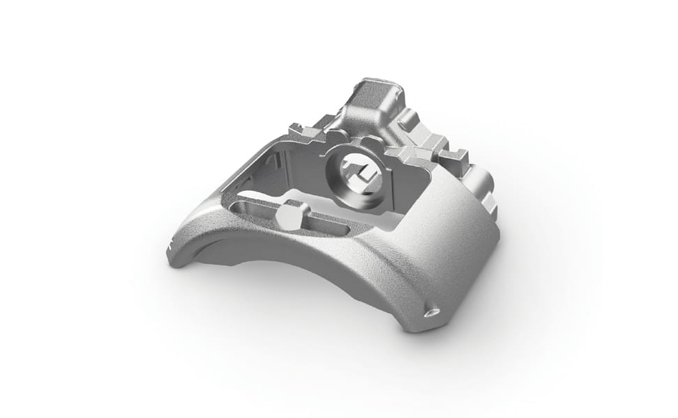
Cast iron


![[New indow]](-/media/2BBAEB19B7CF43A5A42B2C3A137A3E81.ashx)

