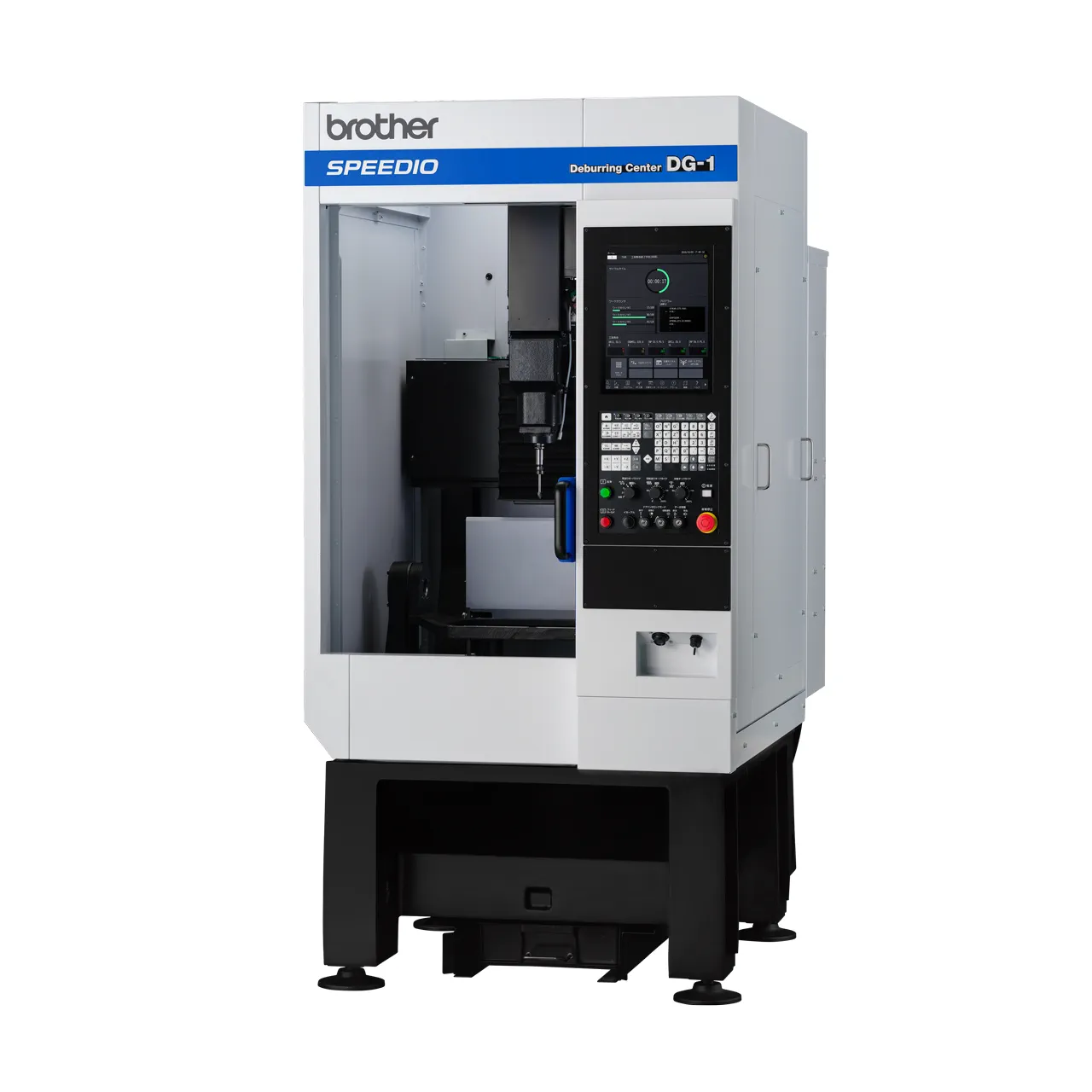
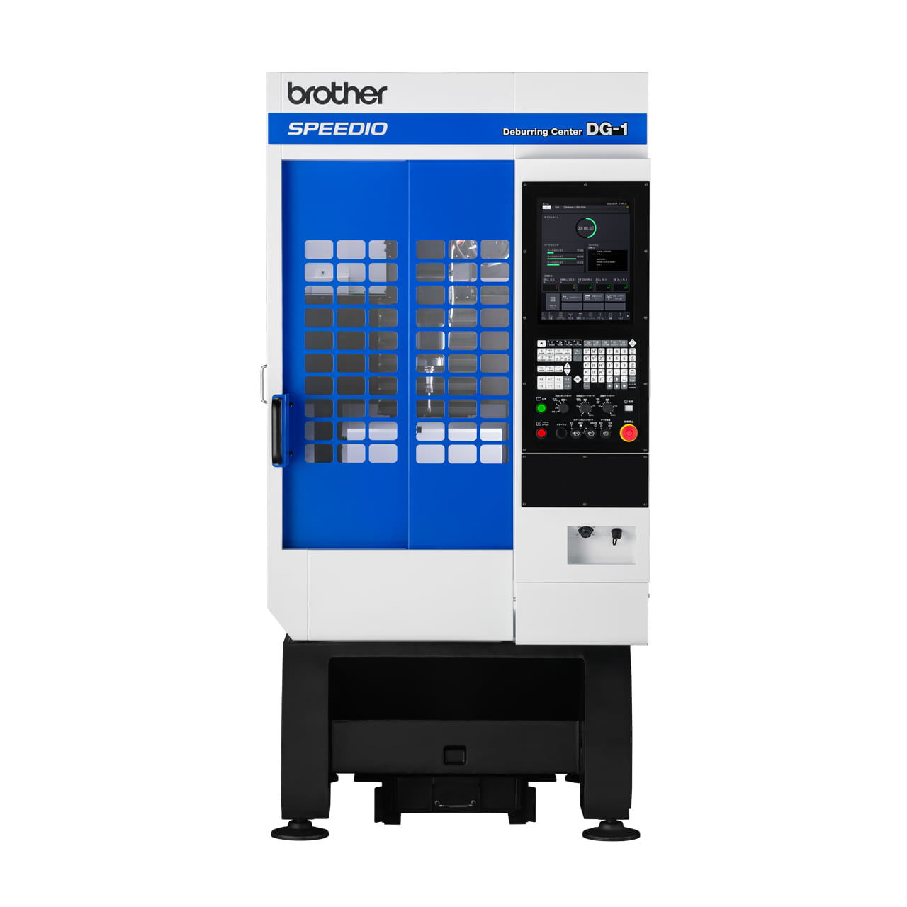
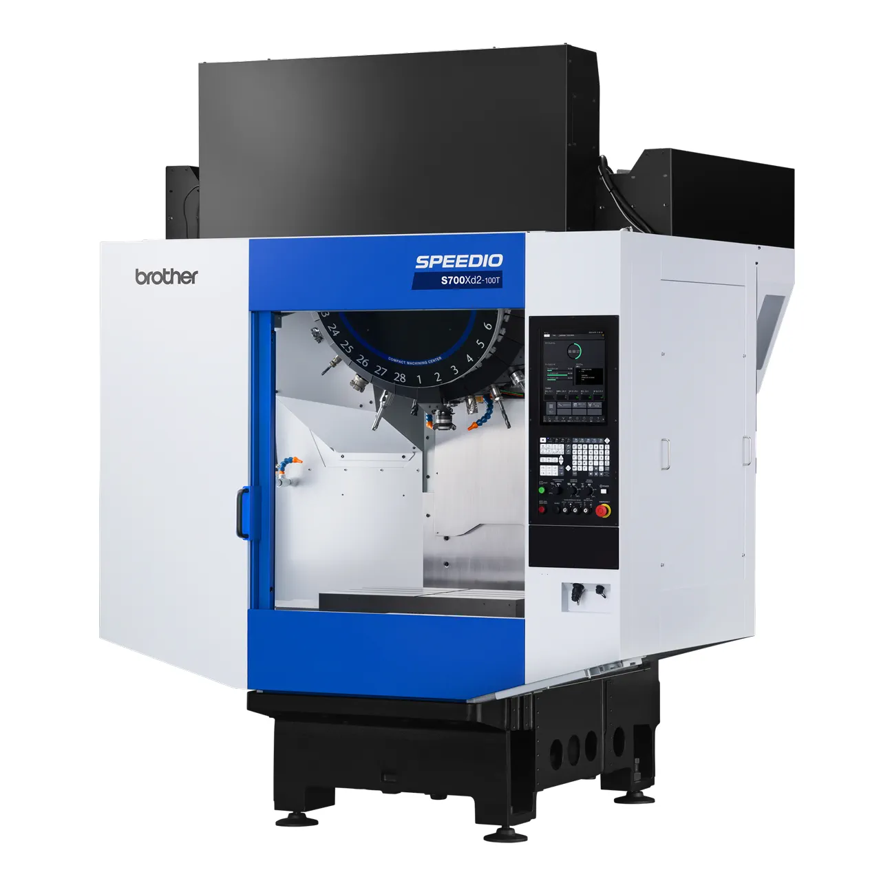
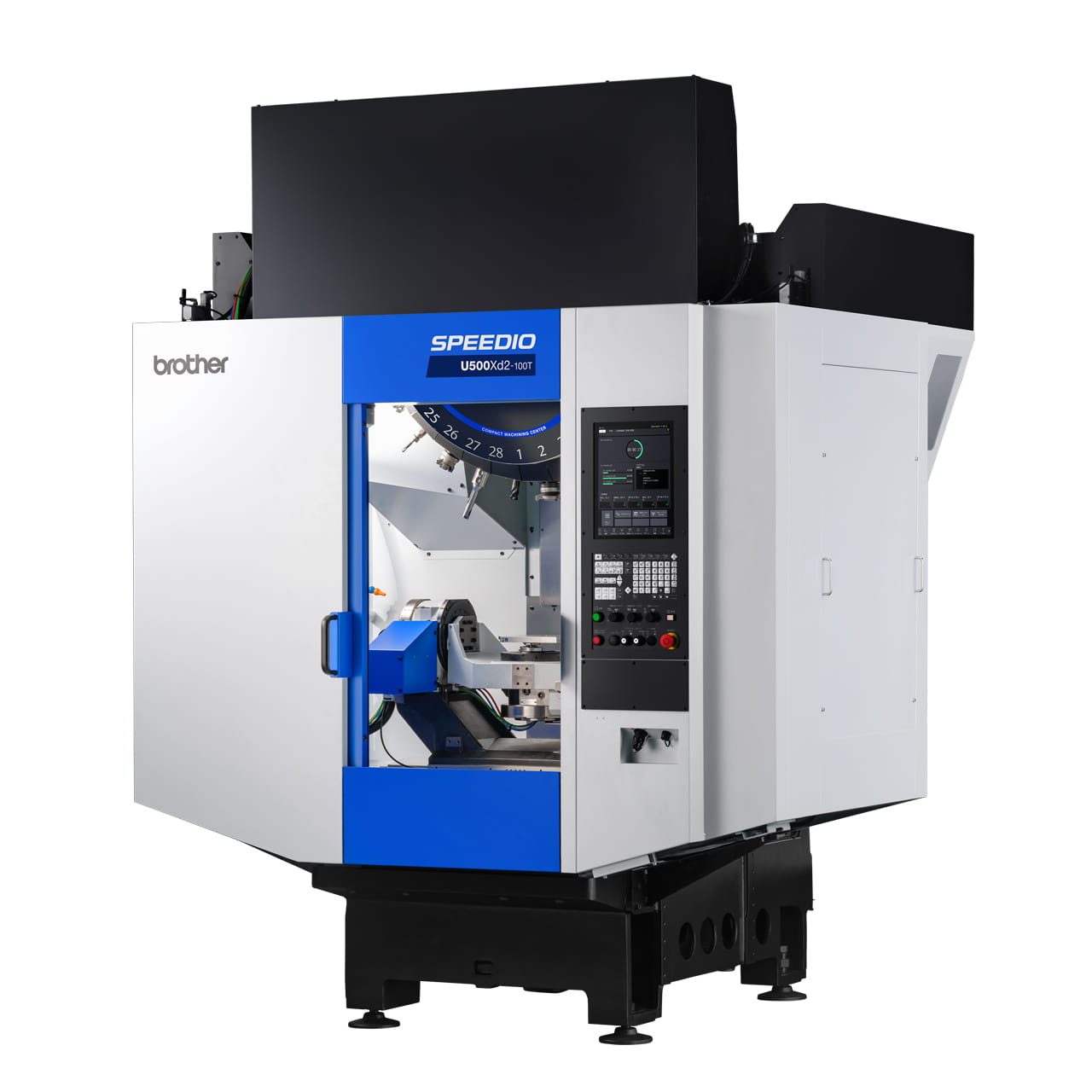
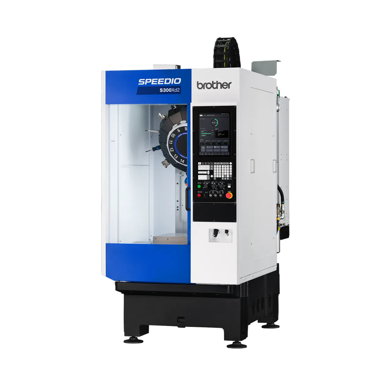
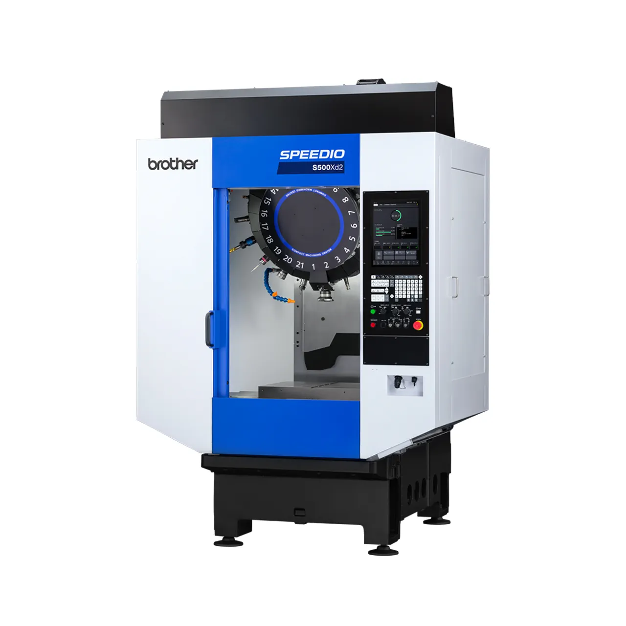
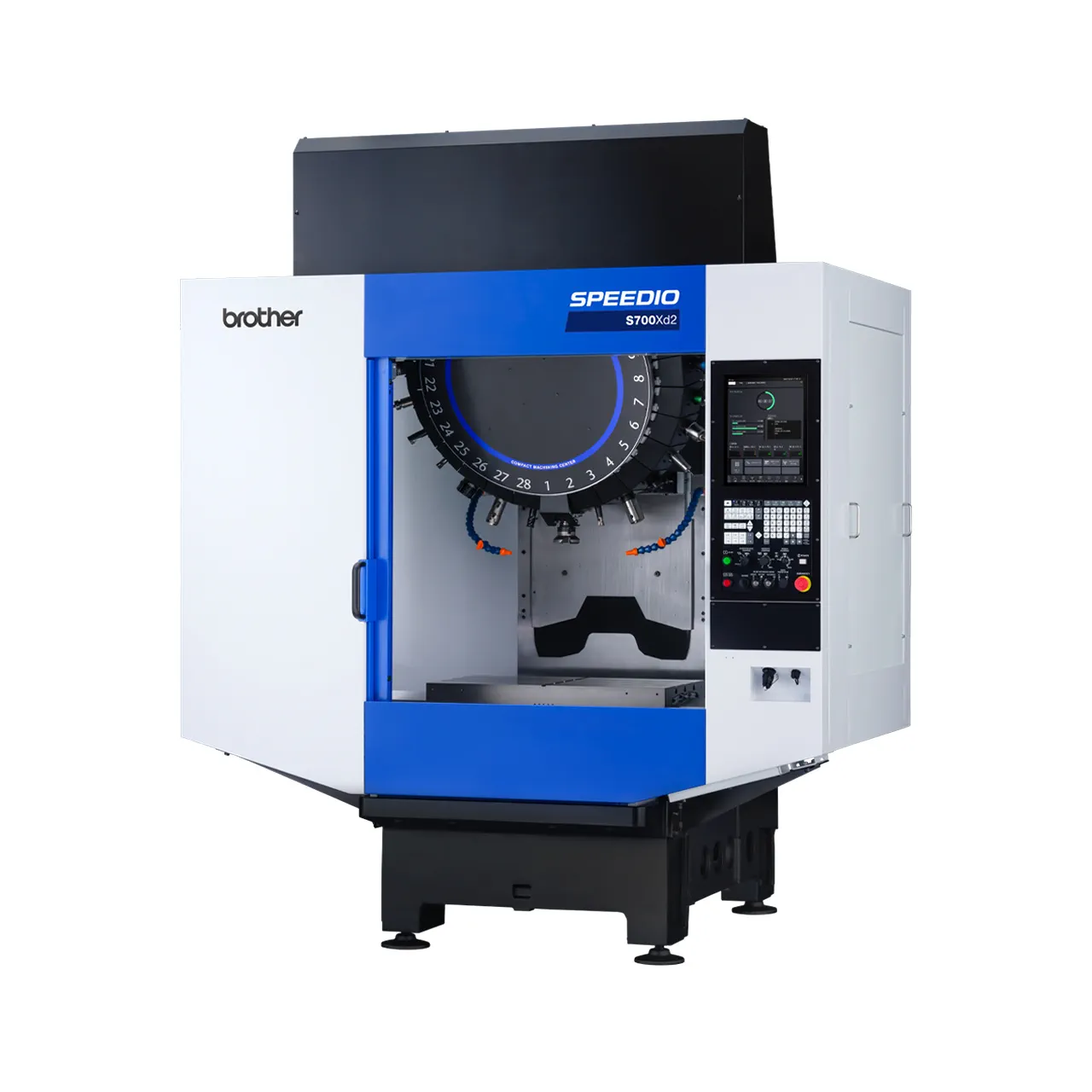
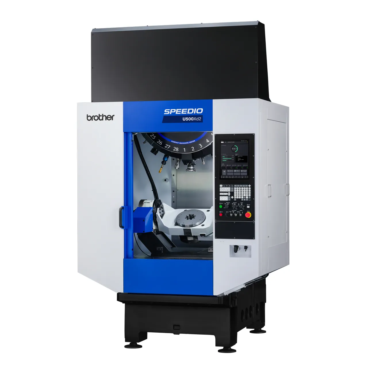
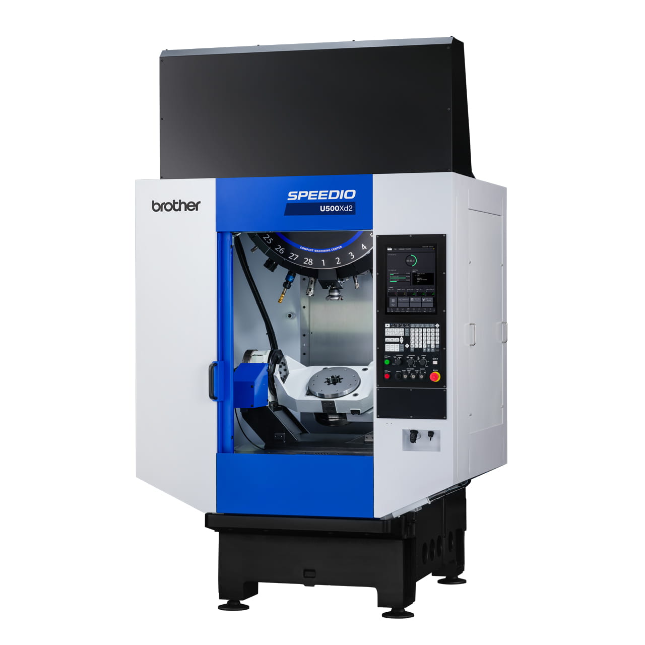
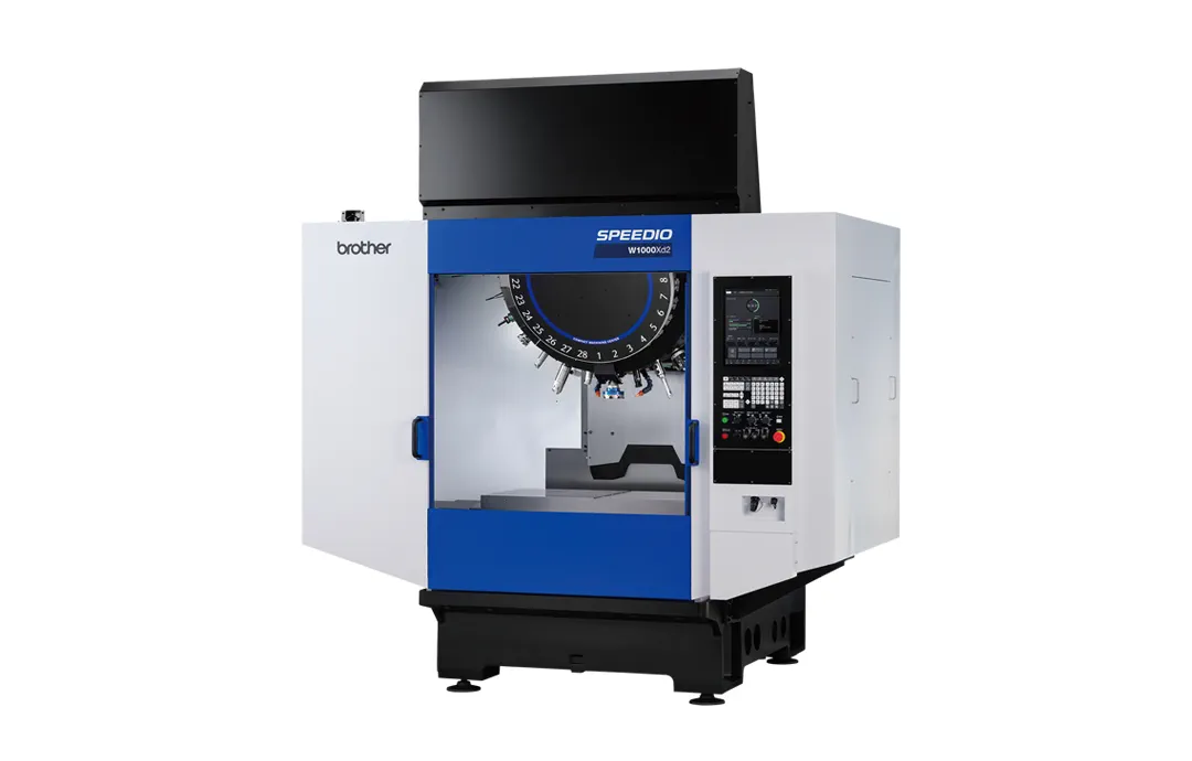
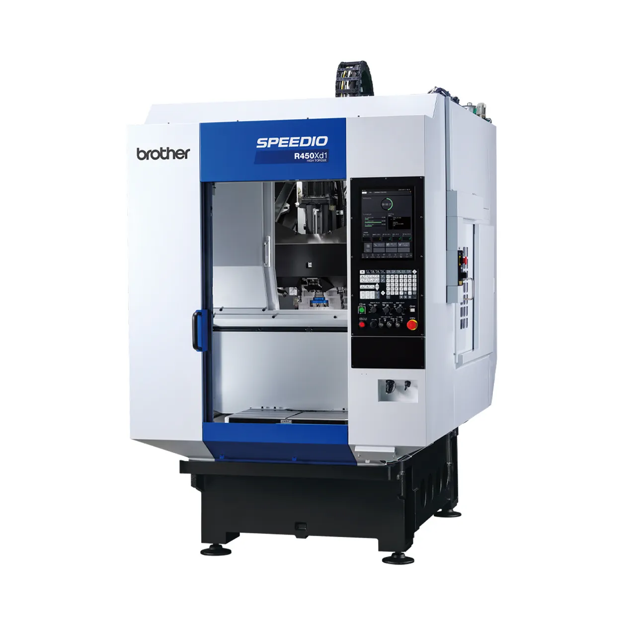
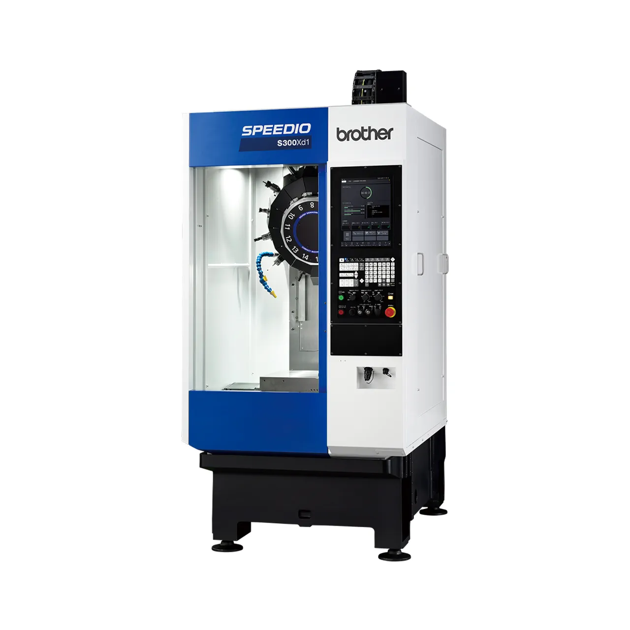
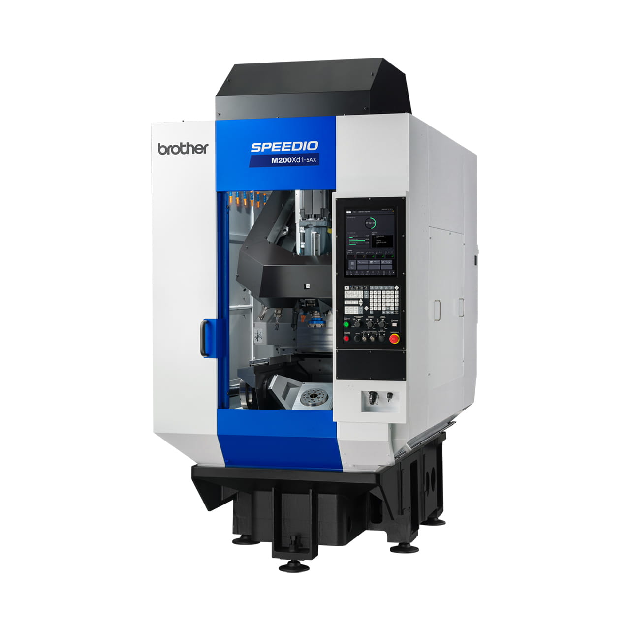
Deburring Center DG-1
Deburring Center
- Travels [mm (inch)]: X: 500 (19.7) Y: 300 (11.8) Z: 275 (10.8)
- Travels (deg.): A: 360
- Max. spindle speed (min-1): 20,000
- Tool storage capacity(pcs.): 6
Mechanizes manual deburring of die casting material in variable-type variable-volume production
Information
Overview
Brother’s original deburring setup functions greatly improve deburring efficiency in variable-type variable-volume production, which is currently performed manually.
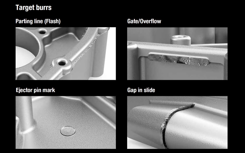
The DG-1 Deburring Center has Brother’s original deburring functions. Simple teaching and correction, and automatic path creation enable fast deburring setup. Optimal machine configuration supports a variety of burr types, and achieves high chip evacuation for dry machining, which encourages mechanization of manual deburring.
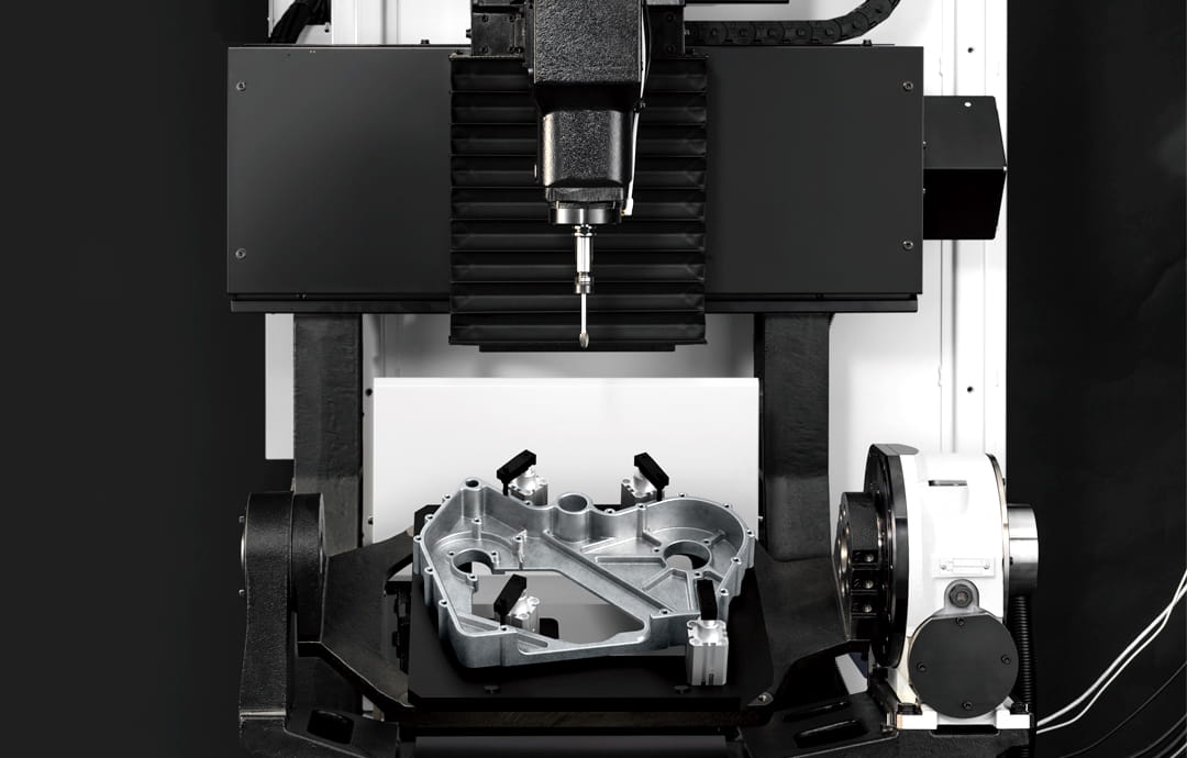
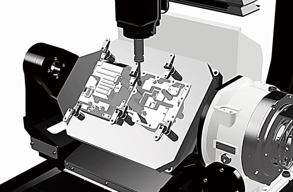
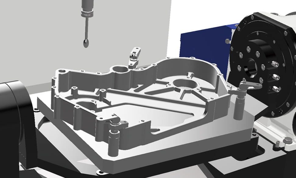
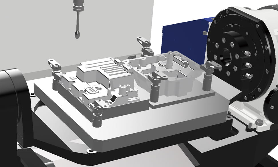
Controlled by four axes, including the tilt axis (A axis) of the roller gear cam structure. Ample jig area is secured, enabling highly flexible jig design.
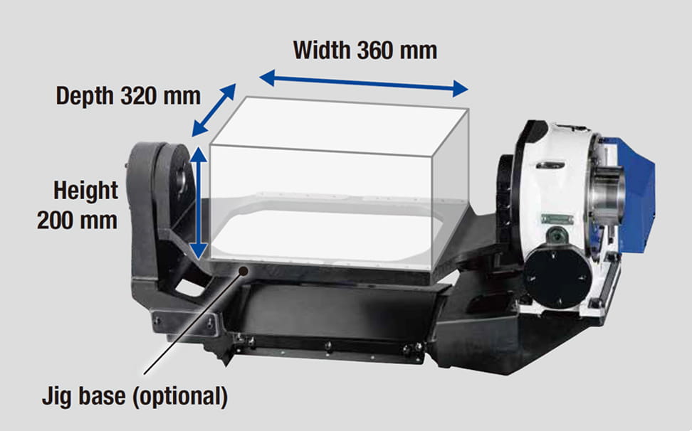
An A-axis table (optional) is available to configure the trunnion jig between the faceplate of the tilt axis and the support.
Mounting range when A-axis table (optional) is selected (reference dimensions)
Waste-free machine configuration enables highly flexible jig design, making it easier to mount jigs for large workpieces or jigs for multi-part machining.
Large workpiece (size: 365 x 270 x 45 mm)
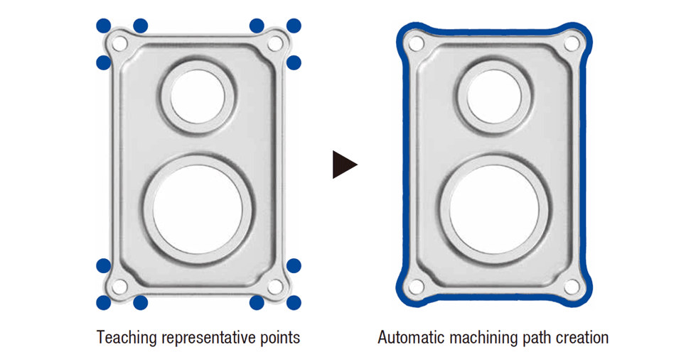
The machine has Brother's original deburring setup functions, including easy teaching of representative points, intuitive path correction, automatic machining path creation, and automatic machining program conversion.
Fast deburring setup has been achieved, enabling mechanization of deburring in variable-type variable-volume production that is currently performed manually.
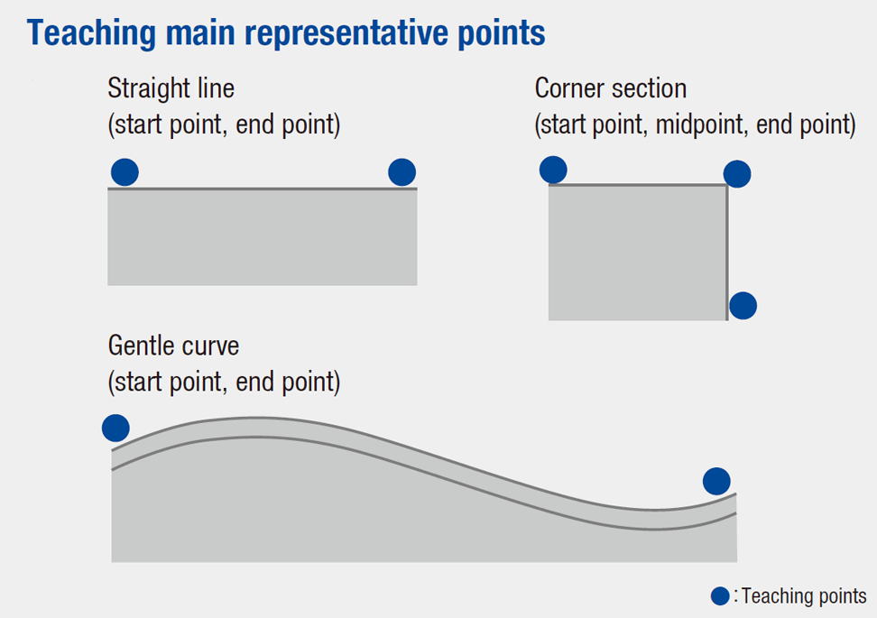
Teaching representative points is conducted by allowing the tool to contact the master workpiece*1. The number of teaching points is less than robots, and there is no need to define straight lines or arcs. For a gentle curve, a machining path can be created automatically by teaching only the start and end points.
*. Please prepare a cleanly deburred workpiece as a master workpiece.
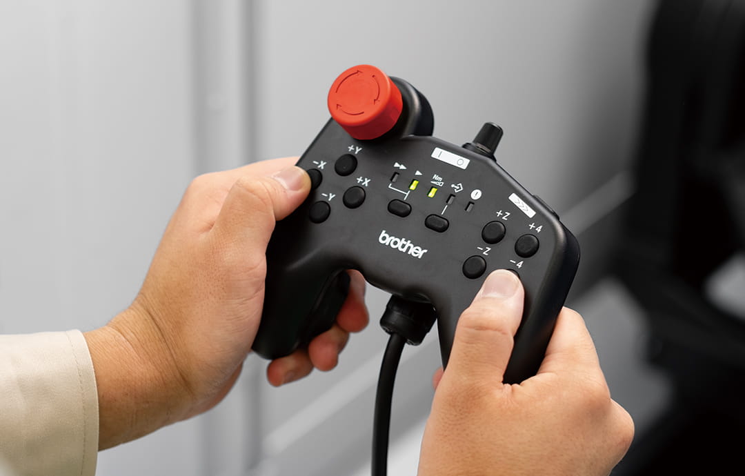
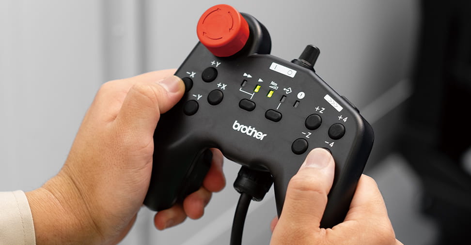
Teaching controller (optional)
Moving direction and speed can be intuitively manipulated to improve the efficiency of teaching representative points.
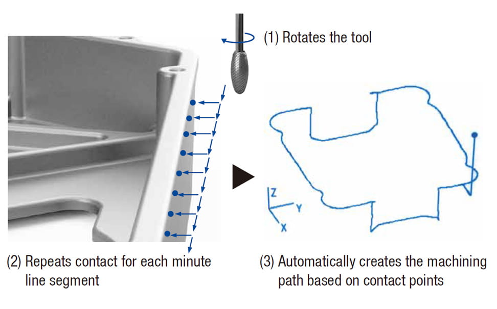
The machining path is created automatically by profiling the master workpiece based on the representative points that have been taught. This requires less correction of the path than robots or machining centers.
Machining path creation image
Based on the representative points that have been taught, the machining path is created automatically by rotating the tool and repeating contact with the master workpiece.
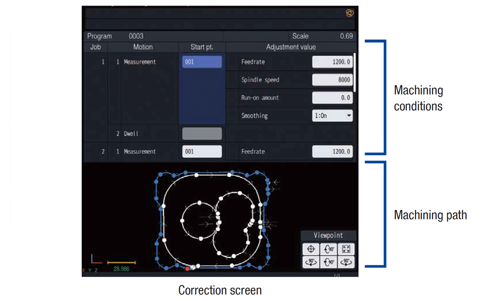
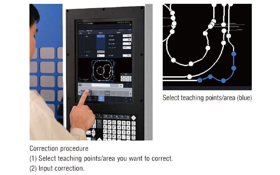
The touch panel can be used to instruct correction points, and the machining path and conditions can be corrected by intuitive operation.
Since correction is possible for each teaching point or area, reteaching, such as required for robots, is not necessary.
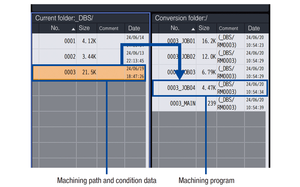
Automatically converts the machining path and condition data into a machining program. No programming expertise is required, enabling easy creation of machining programs. Furthermore, advanced programming with macro programs is also possible by editing the automatically created machining program.
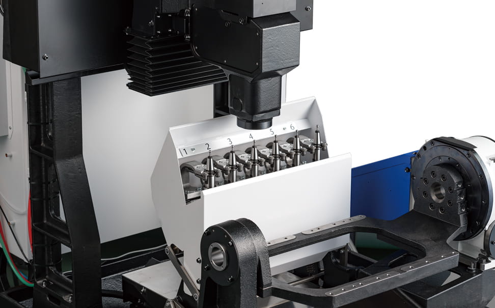
The pickup type ATC can store six tools, and various types of deburring tools can be used. The open/close magazine cover minimizes the impact of chips.
Pickup type ATC
Tool storage capacity : 6 tools Tool To Tool : 3.0s
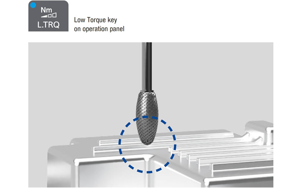
A low torque function is provided to reduce the machine’s travel speed and force.
Even if teaching mistakes are made during teaching of representative points or automatic path creation is affected by teaching mistakes, the machine detects abnormal contact and stops.
This function is enabled by pressing the Low Torque key on the operation panel.
*. This function does not prevent breakage in all collision modes.
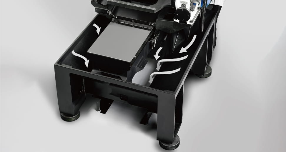
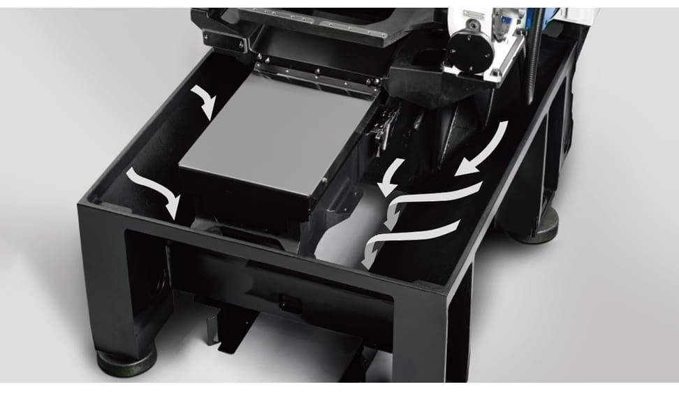
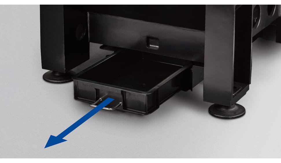
The direct evacuation structure evacuates chips outside the machine. Chips can be easily disposed of by drawing the chip tray from the front of the machine.
Direct evacuation structure
Specifications
Product Specification
Deburring Center DG-1
Max. spindle speed
20,000
Travels
X: 500 (19.7) Y: 300 (11.8) Z: 275 (10.8) A(deg.): 360
Tool storage capacity
6
Rapid traverse rate (XYZ-area)
40 x 40 x 40 (1,575 x 1,575 x 1,575)
Indexing feedrate(A,C)
A: 100
Required Floor Space
998 x 1,656 (39.3 x 65.2)
| Item | Deburring Center DG-1 | ||
|---|---|---|---|
| CNC Unit | CNC-D00 | ||
| Travels | X axis [mm (inch)] | 500 (19.7) | |
| Y axis [mm (inch)] | 300 (11.8) | ||
| Z axis [mm (inch)] | 275 (10.8) | ||
| A axis [deg.] | 360 | ||
| Distance between A -axis rotation center and spindle nose end [mm (inch)] | 80 - 355 (3.1 - 14.0) | ||
| Table | Max. loading capacity [kg (lbs)] | 50 (110) | |
| Max. table load inertia [kg・m2(lb・inch2)] | 0.7 (2,392) | ||
| Spindle | Spindle speed (min-1) | 1 - 20,000 | |
| Tapered hole | 7/24 tapered No.15 | ||
| Feed rate | Rapid traverse rate (XYZ-area) [m/min (inch/min)] | 40 x 40 x 40 (1,575 x 1,575 x 1,575) | |
| Cutting feed rate [mm/min (inch/min)] | X, Y, Z axis: 1 - 30,000 (0.04 - 1,181) *6 | ||
| Indexing feedrate (A) (min-1) | 100 | ||
| ATC unit | Tool shank type | JBS4002-15T | |
| Pull stud type *3 | JBS4002-15P (45°) | ||
| Tool storage capacity [pcs.] | 6 | ||
| Max. tool length [mm (inch)] | 150 (5.9) | ||
| Max.tool diameter [mm (inch)] | 32 (1.2) | ||
| Max. tool weight *1 [kg (lbs)] | 0.4 (0.9) | ||
| Tool selection method | Pickup method | ||
| Tool change time *4 | Tool To Tool [sec.] | 3.0 | |
| Chip To Chip [sec.] | 4.3 | ||
| Electric motor | Main spindle motor (continuous) *2 [kW] | 2.1 | |
| Axis feed motor [kW] | X, Y, Z axis: 0.32, A axis: 0.9 | ||
| Power source | Power supply | AC 200 to 230 V±10%, 3-phase, 50/60Hz±2% | |
| Power capacity (continuous) [kVA] | 3.8 | ||
| Air supply | Regular air pressure [MPa] | 0.4 - 0.6 (recommended value 0.5MPa *5) | |
| Required flow [L/min] | 20 | ||
| Machine dimensions | Height [mm (inch)] | 2,033 (80.0) | |
| Required floor space [with control unit door open] [mm (inch)] | 998 x 1,656 [2,494] (39.3 x 65.2 [98.2]) | ||
| Weight [kg (lbs)] | 1,200 (2,646) | ||
| Standard accessories | Instruction Manual (DVD 1 set), leveling bolts (4 pcs.), leveling plate (4 pcs.), Chip tray, Top cover | ||
- *1 Actual tool weight differs depending on the configuration and center of gravity. The figures shown here are for reference only.
- *2 Spindle motor output differs depending on the spindle speed.
- *3 Brother specifications apply to the pull studs.
- *4 Measured in compliance with JIS B6336-9 and MAS011-1987.
- *5Regular air pressure varies depending on the machine specifications, machining program details, or use of peripheral equipment. Set the pressure higher than the recommend value.
- *6 Value when using high accuracy mode B and tool center point control.
| CNC model | CNC-D00 | |
|---|---|---|
| Control axes | 4 axes (X, Y, Z, A) | |
| Simultaneously controlled axes | Positioning | 4 axes (X, Y, Z, A) |
| Interpolation | Linear: 4 axes (X, Y, Z, A) Circular: 2 axes Helical/Conical: 3 axes (X, Y, Z) |
|
| Least input increment | 0.0001 mm, 0.00001 inch, 0.0001 deg. | |
| Max. programmable dimension | ±999999.9999 mm, ±99999.99999 inch | |
| Display | 15-inch color LCD touch display | |
| Memory capacity | 500 Mbytes, 3 Gbytes (optional) (Total capacity of program and data bank) |
|
| External communication | USB memory interface, Ethernet | |
| No. of registrable programs | 4,000 (Total capacity of program and data bank) | |
| Program format | NC language | |
- * "Control axes" and "Simultaneously controlled axes" indicate the maximum number of axes.
- * Ethernet is a registered trademark of Xerox Corporation in the United States.
| Operation |
Dry run Machine lock Program restart Rapid traverse override Cutting feed override Background editing Screen shot Operation level External input signal key Shortcut key (Optional) Spindle override |
|---|---|
| Programming |
Absolute / Incremental Inch / Metric Coordinate system setting Corner C / Corner R Rotational transformation Subprogram Graphic display |
| High speed and high accuracy |
High-accuracy mode AIII High-accuracy mode BI (Look-ahead 160 blocks) Tool center point control (Look-ahead 1,000 blocks) |
| Monitoring |
Low torque function Overload prediction Waveform display / Waveform output to memory card Production performance display Tool life / Spare tool |
| Maintenance |
Status log Alarm log Operation log Maintenance notice Motor insulation resistance measurement Battery-free encoder Brake load test |
| Automatic / Network |
Computer remote OPC UA Auto notification Built-in PLC (LD/ST/FBD) (Optional) CC-Link, master station CC-Link, remote device station PROFIBUS DP, slave DeviceNet, slave PROFINET, slave EtherNet/IP, slave |
| Energy saving |
Automatic power off Standby mode Automatic work light off |
| Support apps |
Deburring program Adjust machine parameters ATC tool Tool life Waveform display Production performance Power consumption Recovery support Inspection PLC |
| Accessories |
File viewer Notebook Calculator Register shortcut Display off |
| NC language functions |
Menu programming Local coordinate system Expanded workpiece coordinate system One-way positioning Inverse time feed Programmable data input Tool length compensation Cutter compensation Scaling Mirror image External sub program call Macro Tape operation / FTP load operation Multiple skip function (Optional) Interrupt type macro Rotary fixture offset |


